Part 2 – From textual requirements to model and to textual req again
This article is part of a monthly series entitled “Advanced MBSE with SysML and other languages“.
In the first set of articles, this series explains how to use a modeling approach based on the SysML notation to progressively analyze, structure, refine and derive stakeholder needs and requirements into system architecture and lower-level requirements, down to configuration items containing software and hardware parts.
In the second set of articles, this series will focus on the links to other modeling languages used to detail the design and/or perform detailed analysis and simulations to evaluate, verify or validate the virtual representation of the system.
This second article puts a spotlight on the zig-zag between the top-level system requirements, often expressed as text, the system model that will be used to satisfy those requirements through functional and physical architectures, and the lower-level system requirements that can be partially derived from those architectures. We detail why it is important to clearly define the repository of requirements at each stage of the process. Finally, we demonstrate that we can combine the use of a requirement management tool and of a modeling tool to improve the quality of requirements without duplicating the work.
Functional requirements and functions
The functional analysis consists of analyzing the top-level functional needs and requirements and to build one or several functional architectures that satisfy those requirements.
We start by identifying the main functions that satisfy the different functional requirements and we use a traceability matrix to check that each top-level functional requirement has been taken into account by at least one function. Next, we decompose the main functions into lower-level functions that are easier to understand and to manage. This functional breakdown is recursive, down to the level where the leaf function can be fully performed by a component available on the market or internally, or fully allocated to a subsystem (that will be defined by another team).
Let us take the example of a UAV for healthy agriculture, in charge of spraying a treatment solution on crops attacked by pathogenic agents. One of its top-level functional requirements is to treat while flying. I can define a main function called “Fly and treat” that will be in charge of satisfying this top-level functional requirement.
This main function can be decomposed into 2 functional units that address respectively the flight (Follow flight plan at constant speed) and the treatment (Treat the crop). And we can continue the decomposition of these 2 functions…
Now let us look at the way we can use SysML to perform these two activities: traceability and functional breakdown.
When using the SysML notation, we can formalize a function through different concepts:
- The “Block” concept is enough if we are only focused on the structural decomposition of the functions (also called functional breakdown)
- The “Activity” concept is well adapted if we want to use the behavior to identify and decompose the functions
- A combination of both a block and a behavior definition concept (state machine, activity, opaque function ) is useful when we want to have the flexibility to specify the function and its behavior separately.
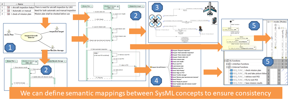
In this article we will use the “Block” concept and we will define a “Function” stereotype to distinguish the functions from components (also based on the “Block” concept). The traceability of main functions to top-level system requirements can be achieved through a “Satisfy” requirements matrix. The Functional Breakdown Structure (FBS) of a given main function can be represented either with a Block Definition Diagram (BDD) or with its dual internal representation, the Internal Block Diagram (IBD).
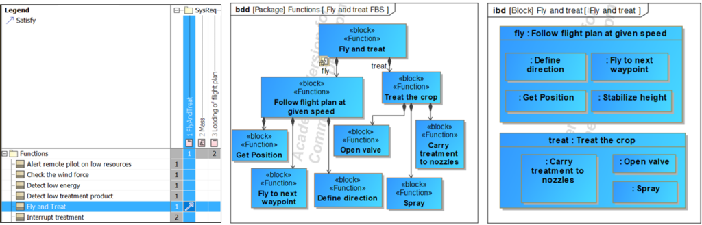
For each new function that has been identified, we specify new functional requirements. This gives us two parallel hierarchies that are strongly related: the functional requirements tree and the functions tree.
And then comes the key question: “Where should I store these new functional requirements? In the SysML modeling tool or in my Requirement Management (RM) tool?”
RM tool and SysML Modeling tool – How can we ensure synchronization?
We are used to manage and store the requirements in a Requirement Management tool. For small projects, such a tool could be Microsoft Word or Microsoft Excel but for large projects, we generally use a dedicated commercial solutions (such as DOORS, DOORS Next Generation, Polarion, Jama, Aras Requirements…). Most of the time, the system specification is entirely built from system requirements managed, documented, and reviewed in this requirement management tool.
If we keep this principle of a dedicated tool to manage requirements, this means that we have to add our new functional requirements into this tool. The challenge is to decide how to distribute the activities between the RM tool and the Modeling tool in order to avoid duplicating the efforts and ensure good consistency between the requirements and functions.
The first option is to use the requirement management tool as the only reference to create and maintain the requirements, at any time, and use the modeling tool only to create and maintain the functions. What about the functional requirements just derived from the functions? Should we put them in the RM tool as soon as we identify them? In that case we need to go back and forth between the RM tool and the SysML tool to ensure the consistency between the new functions formalized in SysML and the functional requirements derived from those functions that have to be created or updated in the RM tool. It means that we need to switch between both tools at every change in the functional architecture. It looks painful… and might be an agility killer…
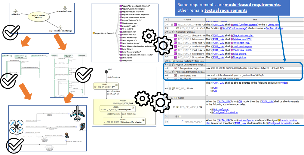
Another option is to create the requirements in the modeling tool, close to the functions they specify, and keep those requirements in the modeling tool until the functional architecture is finalized. If the functional architecture changes (new functions, removed functions, changes in function inputs, outputs, activation in modes, performance…), it is quite easy to adapt the functional requirements because all elements are in the same tool and we can use traceability links to analyze the impacts. When the functional architecture is considered as finalized, then it is time to extract the functional requirements and put them into the RM tool to complete the specification.
If we look at the previous example, we can create a “relation map” diagram that shows the relations between the top-level functional requirement (Fly and Treat), the main functions associated to it, the sub-functions, and a first draft of their associated functional requirements.
Note: The derivation of requirements from a function is an advanced topic that requires some explanation. Here we show the derivation of only ONE basic (draft) requirement for simplification but a function generally leads to the identification of several requirements, built from the combination of function performance criteria and lifecycle “situation” (phase/mode/state… and conditions) in which the function is active. And each of the identified requirements will later be completed to prepare its verification, leading to an improvement of the requirement maturity and quality.
The derivation of requirements will be detailed in a future dedicated article.
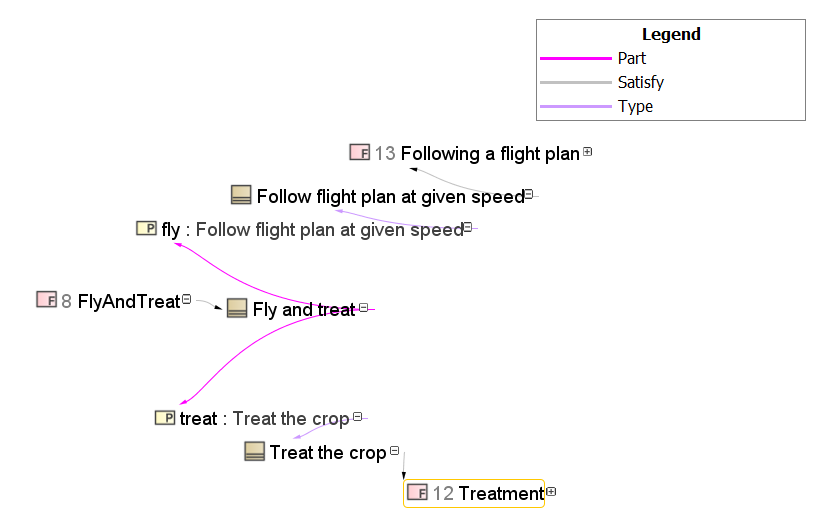
Note: the relation map can be read through the following sequence of relations: the top-level functional requirement (FlyAndTreat) is satisfied by a Function (Block) that is composed of the two sub-functions fly and treat (part properties) that are each typed (defined) by a function (block) that satisfies requirements.
So far, so good. But what happens if one of my colleagues is defining some lower-level functional requirements in the RM tool while I’m defining my functional breakdown in the modeling tool? We are simply doing the same exercise concurrently through 2 different means and in 2 different tools: refine the functional requirements. Double efforts for the same value…
You may smile at this situation but it is something that happens regularly in the industry, especially when the modeling activity has not been defined in the development plan. So it is necessary think about it. The important principle is to ensure that there is only one reference for the modification of the requirements at a given stage of the development process.
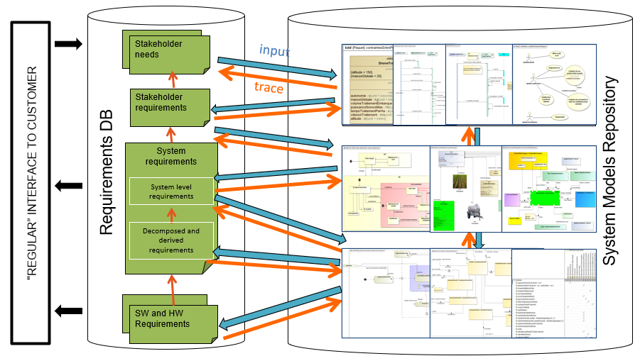
When using the second option, we have requirements managed in two repositories. Thus, it is necessary to clarify which requirements can be modified by which tool to conform to this important principle:
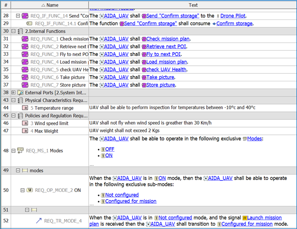
- The top-level functional requirements are defined and maintained in the RM tool and propagated in the modeling tool
- The lower-level functional requirements are defined and maintained in the modeling tool and propagated later in the RM tool
This approach makes things clear by using only ONE requirement repository at a given stage. It allows an efficient definition of the requirements by using different tools according to each stage.
We suggest 3 different stages to organize the responsibility in the modification of the requirements:
- Before the SRR (Systems Requirements Review): the RM tool is used to define and document all top-level system requirements
- During the elaboration of the functional architecture: the modeling tool is used to define and document lower-level (refined) functional requirements derived from the functions. This stage ends with the preparation of the Preliminary Design Review (PDR).
- Since the preparation of the PDR: the RM tool is used to gather all system requirements including the ones coming from the functional model in order to ease the review of all system requirements and to generate the complete system specification.
In order to support this distributed work on requirements through 2 different tools, we also need to ensure that we can propagate the requirements between tools in an easy way. This question is addressed in the next chapter.
Can we automate the transfer of requirements between tools?
The answer is yes for many situations.
If you use Cameo Systems Modeler as a SysML modeling tool, you may know that 3DS provides a third-party tool called “Cameo Data Hub” that is able to synchronize objects between DOORS and some other RM tools and Cameo Systems Modeler. Clearly this is a good solution to ensure that requirements are aligned between both tools at a given point in time.
But this is not enough. We also need the traceability between top-level and lower-level system requirements. If we place lower-level requirements in DOORS without traceability to top-level requirements, then the modeling may be considered as useless and a waste of time and efforts. Traceability is very important because it gives us a powerful means to analyze a change in top-level requirements and immediately identify the lower-level requirements on which there may be impacts.
The idea is simple: let us extract this traceability from Cameo and let us create direct links between both levels of requirements as we would have done directly in DOORS. A small CSM plugin can do this: extract the traceability chain and recreate the direct links instead of using intermediate modeling elements (the functions).
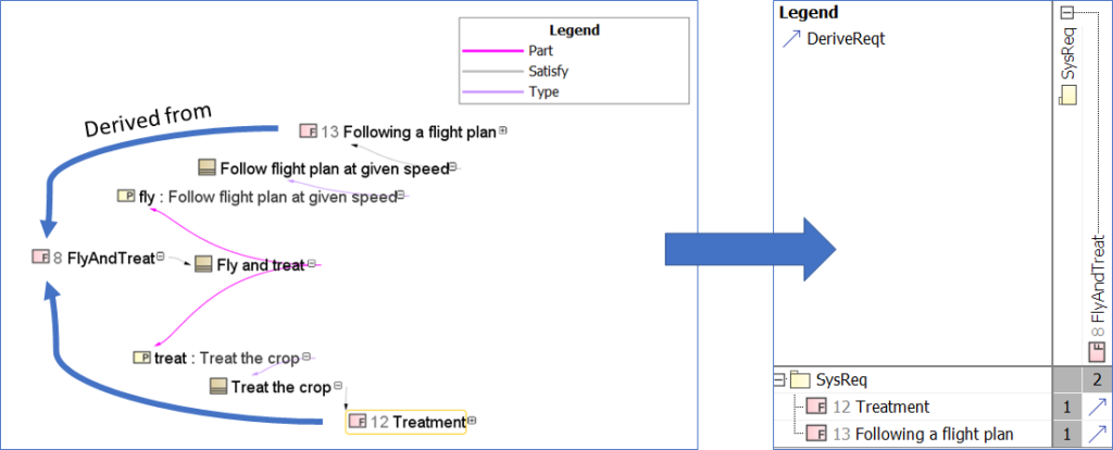
Once this is done, we can synchronize both the lower-level requirements and their traceability links to top-level requirements between CSM and DOORS.
That’s it! Finally, we get our 2 levels of requirements in DOORS with traceability exactly as if we had worked only in DOORS. But we have in fact used CSM to help us in building a functional architecture as an intermediate step, which leads to a far better quality of the requirements once put back in the RM tool!
Zig zag with synchronization and automation in practice (video)
This short video shows the presented zag zag pattern between the RM tool and the SysML tool in practice.
Note: the derivation of lower-level requirements is very basic in this video (as it was not the main topic and we did not want to spend time on it). There will be additional material on this topic at a later date.
Next articles to come…
- June 2020 – Early validation of stakeholder needs through simulation
- July 2020 -Consistency between functional and logical architectures
- August 2020 – Minimization of the coupling in the logical architecture
- September 2020 – Digital continuity between SysML and Simulink
- October 2020 – Digital continuity between SysML and AADL
- November 2020 – Digital continuity between SysML and Modelica
- December 2020 – Co-simulation of SysML and other models through FMI
Previous articles in the series
- April 2020 – Formalization of functional requirements