Part 7 – Digital continuity between SysML and AADL
This article is part of a monthly series entitled "Advanced MBSE with SysML and other languages".
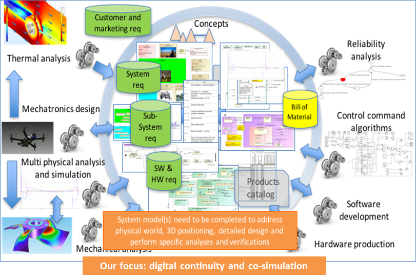
In the second set of articles, this series explains how to complete the top-level system definition model, formalized in SysML, with other modeling languages and tools, considered as more efficient to perform the system detailed design or certain kinds of system analysis. Focus is put on digital continuity with guidelines concerning coupling semantics and coupling automation between languages and tools.
In this article 7, we start from a System Definition model developed with SysML and we present an approach, which uses real-time architecture specialised language to refine this definition into an Electric / Electronics and Software Architecture. We use AADL (Architecture Analysis Description Language) as an example, but we could use languages with similar concepts and purposes such as AUTOSAR (used in automotive industry) or UML MARTE.
We present the allocation of timing budgets on SysML models, starting from operational scenarios, and through the concept of Functional Chains. We refine these timing requirements through the definition of physical components and a physical architecture formalised with AADL.
Executive Summary
Context elements
In the previous articles (part 1 to part 5), we have introduced a method based on the SysML notation to support the following systems engineering activities :
- Formalization of functional needs
- Refinement and definition of systems requirements
- Early validation of stakeholder’s needs using Functional Simulation
- Definition of Functional and Logical Architectures
- Optimization of Logical Architectures
This article starts with the availability of a logical architecture for a case study called AIDA (that comes from the Saint Exupery Research Institute). It is illustrated below:
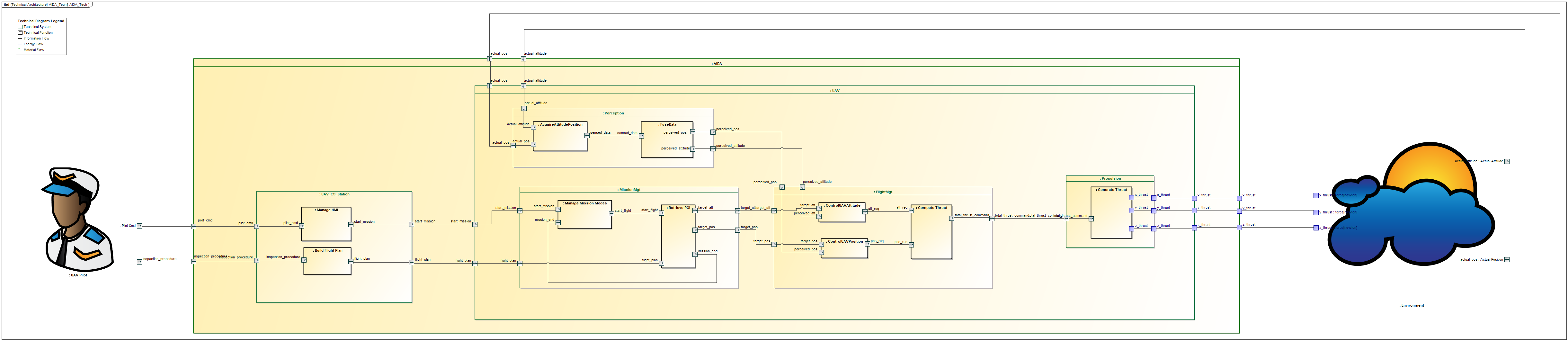
AIDA Logical Architecture
End to End Timing requirements and Functional Chains concept in SysML
End to end timing requirements are very important non-functional requirements (amongst others) to consider in order to reduce the solution space and to choose the appropriate physical solution. An end to end timing requirement generally specifies the acceptable maximum timing duration expected from an input to a specific output (of a function or a system) following a specific flow path in a specific operational scenario. End to end timing requirements may be imposed by a Stakeholder Requirement or may emerge as a System Requirement to satisfy a Stakeholder Requirement.
Functional chains are playing a key role to specify end to end timing requirements. A functional chain may be seen as an abstraction of a set of execution paths from an SoI’s input to an SoI’s output. In this article, we propose to formalise a functional chain with a SysML block, and the end-to-end timing requirement with a time duration constraint element directly available in the SysML notation, as illustrated below:
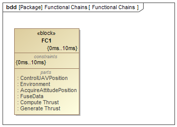
End to end timing requirement on a functional chain
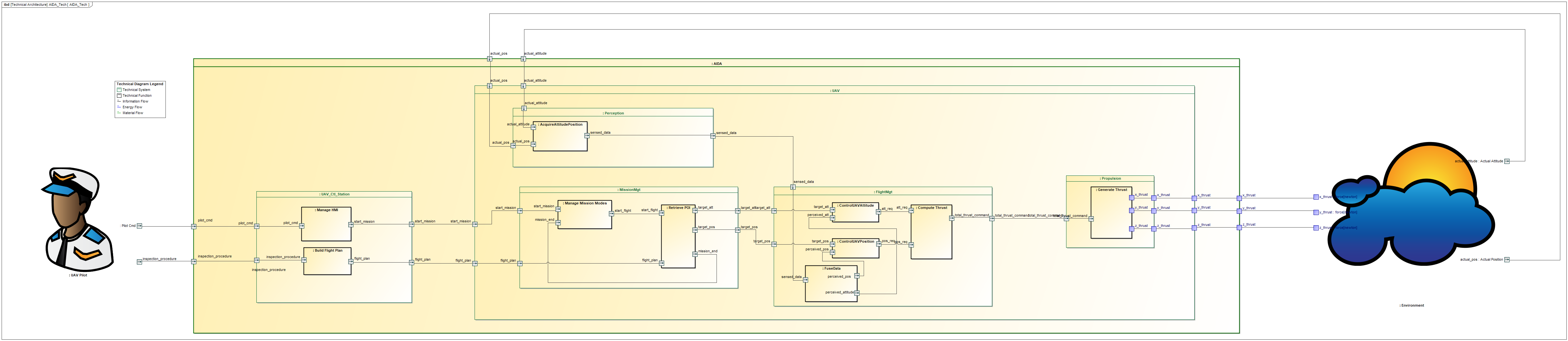
Then, we propose to show the realisation of the functional chain with a SysML IBD Diagram. This diagram allows to visualise the end-to-end flow from the selected function/System input(s) to the selected function/System outputs. Each function’s input and output that participate in the functional chain are linked with a dependency link
As an example, the following IBD diagram focuses on the functional chain that controls the position of the UAV and the required thrust value. The end to end timing requirement applies to the whole functional chain, which means in our example that the final solution shall take less than (or equal to) 10 ms to perform the loop. Therefore, it is necessary to divide the timing budget and to allocate a time duration to each function in order to find a solution that can satisfy this requirement.
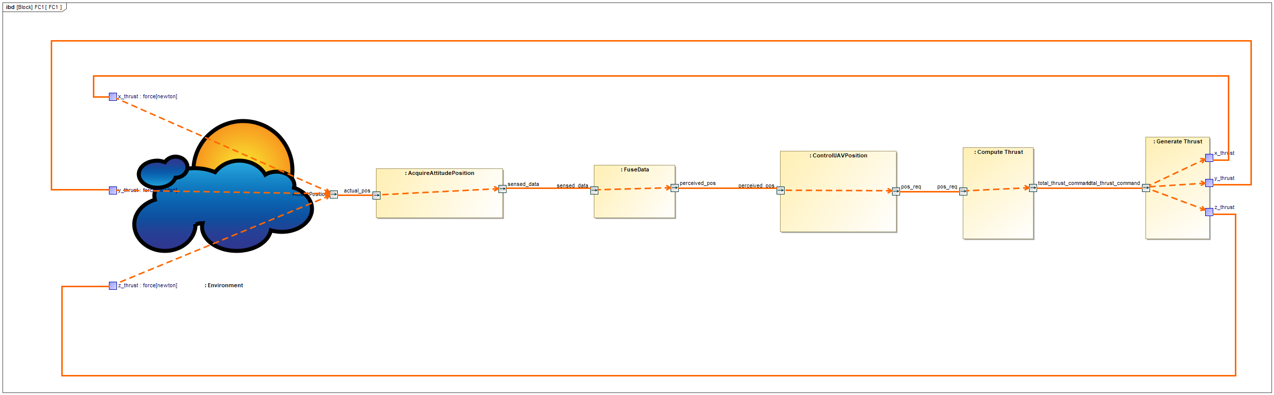
Functional chain for control loop
In practice, the proposed process consists for the System Engineer in defining timing requirements as budgets for all the elements of the overall chain. Then, Systems Designers will have to demonstrate how their selected design meets these execution budgets. This is where we suggest to use AADL language to refine timing properties induced by selected hardware components and software properties. The next paragraph quickly presents the AADL language and the following paragraph provides an application on our example.
AADL Language overview
AADL (Architecture Analysis and Design Language) is a language dedicated to the modeling and analysis of real-time, safety critical, embedded systems. It is a standard published by the Society of Automotive Engineers as reference AS5506C.
The AADL language relies on both graphical and textual syntax and it includes the following concepts and extensions:
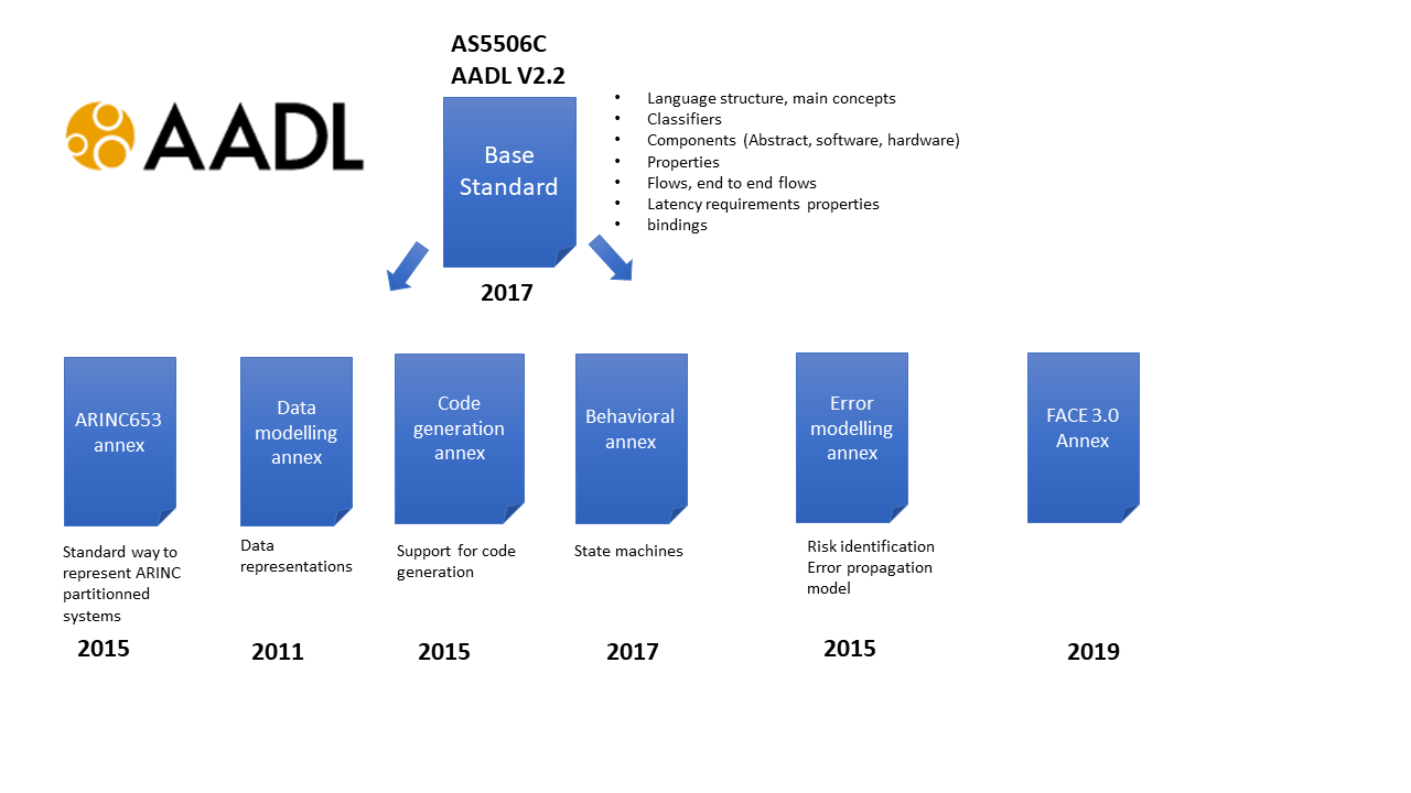
In this article, we focus on the following Base Standard concepts:
- Structure Concepts:
- Abstract Components
- Software Components (Processes, Threads and Subprograms)
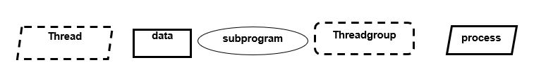
pictures from AS5506C standard
-
- Software Timing properties (periods, priorities, …)
- Hardware Components (Processors, Devices and Buses)
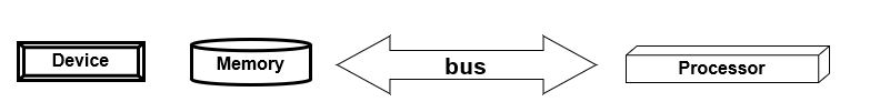
pictures from AS5506C standard
-
- AADL Ports
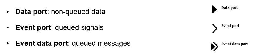
pictures from AS5506C standard
-
- Data Types
- Connections Properties
- End to End flows and associated latency requirements:
- concept of end to end flow (from specific input to specific output) and definition of latency requirements
- concept of latency on flows
- Bindings:
- concept of mapping of functions (abstract components) to software elements
- concept of mapping of software components to hardware components elements
Application on the AIDA case study
To illustrate the full approach, we use a simplified model of an Unmanned Aerial Vehicle (UAV) based on the AIDA case study developed at the St-Exupery Research Institute. We use the following languages and tools:
- CAMEO Systems Modeler 19.0 SP4
- AADL Inspector from Ellidiss
- STOOD for AADL from Ellidiss
And Hardware architecture has been defined with inspiration from crazyflie aadl architectural model.
The AIDA Logical Architecture in SysML has been recalled at the beginning of this article. Here we put the focus on the UAV system and in particular the co-design of the electric/electronic and distributed software architecture.
The functional goal is to control the actual position of the UAV to fit the expected trajectory around the aircraft. Therefore, one must find the right control parameters so that the UAV can follow the expected trajectory within an expected maximum timing latency. Then, we want to verify the compliance of the selected hardware and software architecture to the timing requirements.
Recall of the AIDA Functional and Logical Architectures
The AIDA Functional Architecture is defined in SysML and presented below:
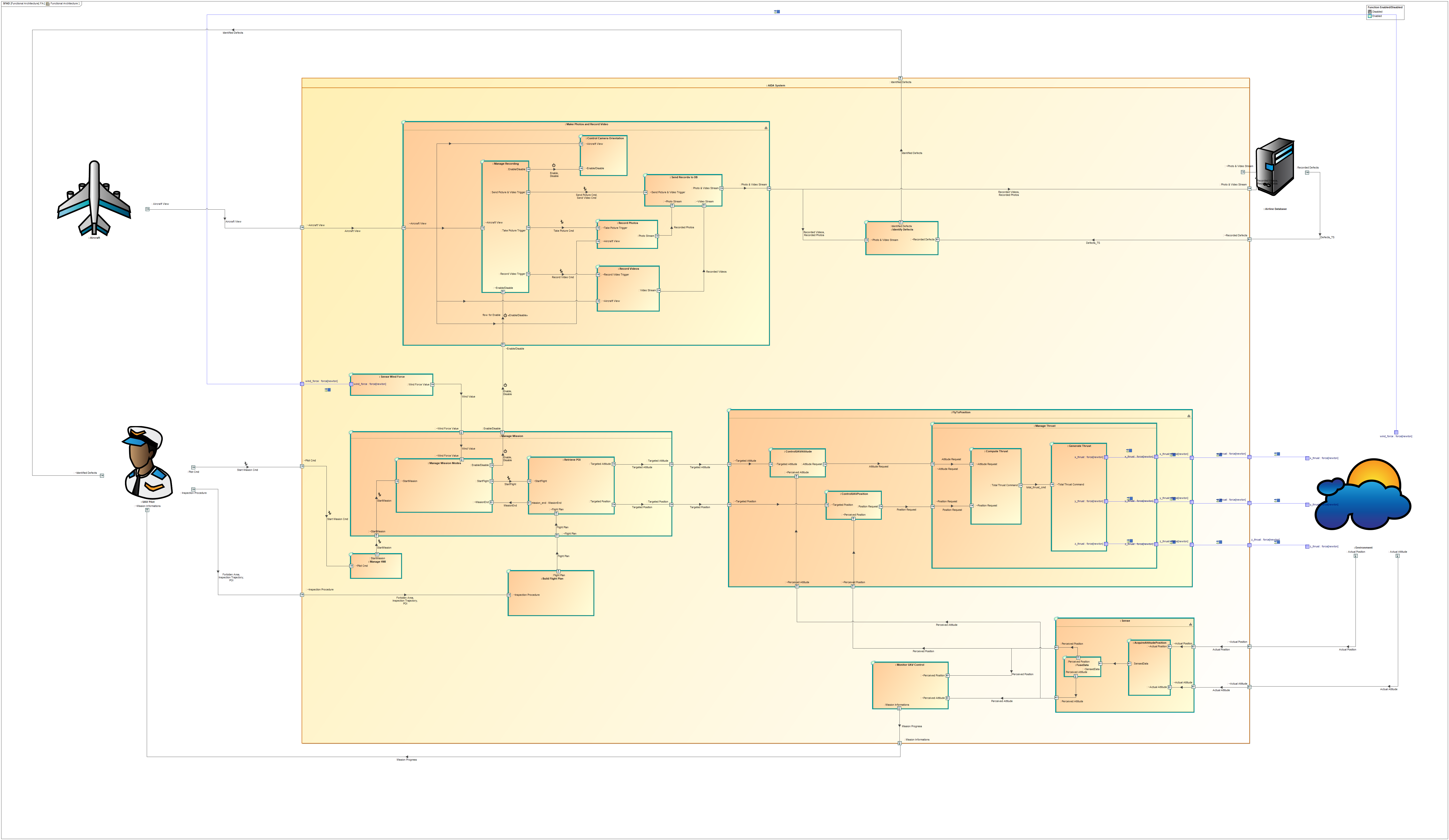
AIDA Functional Architecture
In this functional architecture, we detail the position and attitude control functions, as well as the compute thrust and generate thrust functions of the UAV.
The logical architecture is established with regards to emerging systems and sub-systems decomposition. In this example, we decompose the UAV into the following subsystems:
- Perception Subsystem
- Flight Management Subsystem
- Propulsion Subsystem
- Mission Management Subsystem
Then, we allocate the functions to the subsystems as follows:
AIDA Logical Architecture
Definition of Timing Requirements (end to end latency) in SysML
Next, we define the expected maximum latency of the measurement to thrust force control (performance of the control loop) in a specific functional chain defined in SysML, as presented below:
Functional Chain for Control Loop
This chain is extended with the duration constraint property defined with a range of valyues between min and max values. In our example: 0ms .. 10ms.
Initiate Logical Architecture in AADL
From this step, we perform the design of this system using the AADL language to support software design by taking into account hardware constraints and performing timing verification.
The first step is to translate the functional/logical architectures and functional chains defined in the SysML language toward a logical architecture using the AADL language. This step results in an AADL System Implementation using Abstract Components and end to end flows as illustrated below:
Resulting AADL Architecture from SysML Logical Architecture
In order to perform this translation, we convert our SysML Flow of Information of type “Trigger” into Event and Flow of Information of type “Data” in AADL Data exchanges. The functional chain is converted to the equivalent concept of AADL end to end flow with latency specification.
| System Engineering Concept | SysML Concept | AADL Concept |
|---|---|---|
| Function | Block | Abstract Component |
| Technical System Element | Block | Abstract Component |
| Trigger Port | Port | Event Port |
| Enable/Disable Port | Port | Event Port |
| Any other Port (Data, Material or Energy) | Port | Data Port |
| Internal Dependency Relation | Dependency | Flow path |
| End to End Functional Chain from operational scenario | Block, IBD | End to end flow |
| Functional Chain Duration | Time Duration Constraint | Latency |
| Functional Flow | Connector | Port Connection Feature |
Define Hardware / Software components that fit with the logical architecture
Once we have created a logical architecture in AADL that is semantically equivalent to the SysML logical architecture, we can start exploring the physical architecture definition using AADL concepts.
We initiate the Physical Architecture from the Logical Architecture and start to design Physical Components (defined as System Components in AADL), one for each Subsystem:
- Mission Mgt Sub-System
- Perception Sub-System
- Flight Mgt Sub-System
- Propulsion Sub-System
Now we can explore the different physical technical solutions able to refine this logical architecture and we determine the appropriate physical components (hardware and software) which satisfy all the requirements (functional and non-functional such as timing requirements or expected temperature range, safety level of selected devices, constraints due to selected solutions, …).
This exploration space is wide and shall be done carefully with regards to the compatibility of the physical interfaces. In the following example, we select a design solution to minimise the cost and timing execution of the Flight Control Management from Targeted Attitude and Position input up to the generation of the Thrust Force. The engineering goal is to move the UAV with an expected maximum timing budget of 10 ms.
With this design, we propose a mapping from Sub-Systems to Physical Components as follows:
- Mission Mgt and Flight Mgt are implemented by the FlightMgtController System Electronic Control Unit (Hw and Sw components)
- Propulsion Sub-System is implemented by a PropulsionMgt System which is composed of 4 Electrical Motors and associated Propeller / Power adapter.
- Perception Sub-System is implemented by a Sensors_Module System which is composed of an integrated circuit which implements 3 sensors (accelerometer, gyroscope, magnetometer).
Note : In the Logical Architecture, the Perception Sub-System shall eprform the following internal functions:
- SenseAttitudePosition
- FuseData
According to the expected performance and available/selected technologies, some sensors may provide hardware support for FuseData. In the proposed solution we perform the selection based on costs, so we decide to perform FuseData using dedicated software and we allocate the FuseData function to the Flight Controller instead of Sensors module.
Define Hardware / Software architectures and bind them to the logical architecture
Then, we can design the software architecture while taking into account hardware constraints, and study the technical solutions to implement the logical components (selection of appropriate devices and processors, decompose functions into several processes, allocate processes to one or more processors, define interaction between the software and hardware elements, …). At this stage, hardware and software engineers shall analyse the suitability of the architecture regarding functional and non-functional requirements (such as timing requirements).
For this article, we propose a simplified electronic architecture using the following physical components :
- One MPU9250 device for Attitude/Position sensing usable with I2C interface. This device integrates the following sensors:
- Accelerometers : Digital-output triple-axis accelerometer with a programmable full-scale range of ±2g, ±4g, ±8g and
±16g and integrated 16-bit ADCs - Gyroscope : Digital-output X-, Y-, and Z-Axis angular rate sensors (gyroscopes) with a user-programmable full-scale range of ±250, ±500, ±1000, and ±2000°/sec and integrated 16-bit ADCs
- Magnetometer: 3-axis silicon monolithic Hall-effect magnetic sensor with magnetic concentrator
- Accelerometers : Digital-output triple-axis accelerometer with a programmable full-scale range of ±2g, ±4g, ±8g and
- One 32 bits FlightController Processor for FlightControl functions execution: STM32F7x5
- One 32 bits Connectivity Processor for Connectivity features (BlueTooth Low Power mode): STM32WX5
- 4 electrical motors controlled by PWM outputs from the Main Processor
- 1 UART bus for communication between the Main Processor and Companion
With those choices, we suggest the following AIDA HW Architecture:
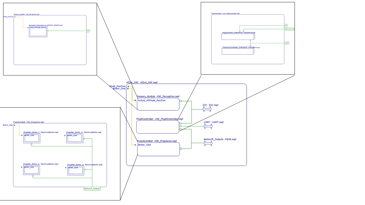
AIDA Hardware Architecture in STOOD for AADL
For software design, we suggest decomposing the software in 2 processes (connectivity and flight management). This is mainly due to the following elements:
- Different criticality level between the 2 software applications
- Different timing constraints between the 2 software applications
- Limited computing power to execute the both applications on one processor
- The main processor does not support all the required connectivity and interfaces
That is the reason why, in this proposal, we have performed the following decomposition:
- One Process dedicated to the Connectivity Stack (focus on communication interfaces with Uav Ctl Station and Pilot)
- One Process dedicated to FlightMgt related functions:
- Thread MissionModesMgt: implements RetrievePOI and MissionMgtModes functions
- Thread FlightControlLoop
- ControlUAVAttitude: implements Control UAV Attitude function
- ControlUAVPosition: implements Control UAV Position function
- ComputeThrust: implements Compute Thrust function
- Thread Driver I2C MPU9250: implements the interface with the Attitude Sensors Devices and functions of Perception Subsystem (AcquireAttitudePosition and FuseData)
- Thread CommunicationMgt: implements the communication interface with the Connectivity processor
- Thread Propeller Interface: implements the interface with the electrical motor command (PWM)
The proposed AIDA SW Architecture is presented below:
AIDA SW Breakdown Structure
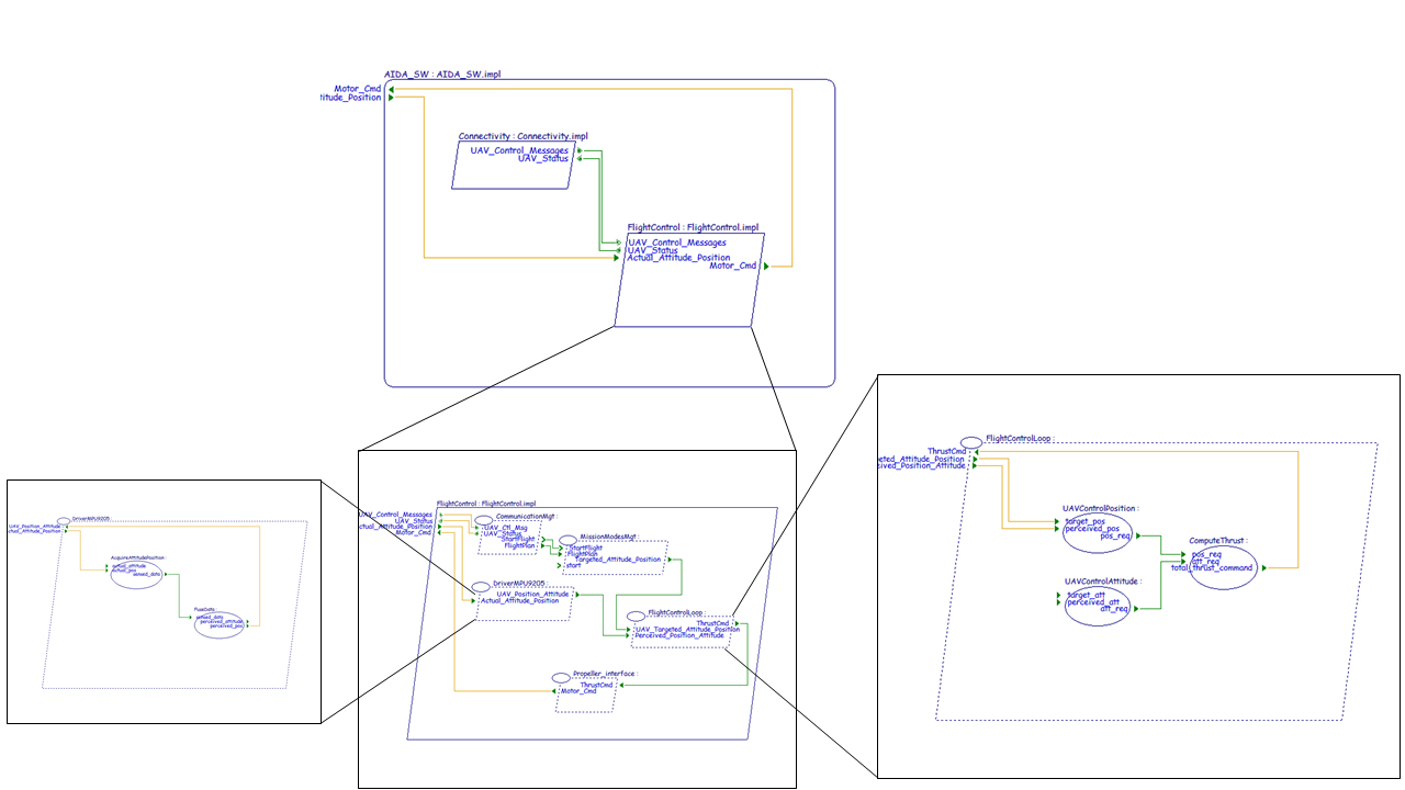
AIDA SW Architecture in Ellidiss STOOD for AADL
Finally, we can perform the binding in a 3 steps process:
1. Allocate Software Processes to Hardware Processes
2. Perform correspondence/allocation between Abstract components (translated from SysML logical components) and Hw/Sw components.
3. Verify the consistency of the design by checking that all the logical components are bound to the Processes and the hardware components.
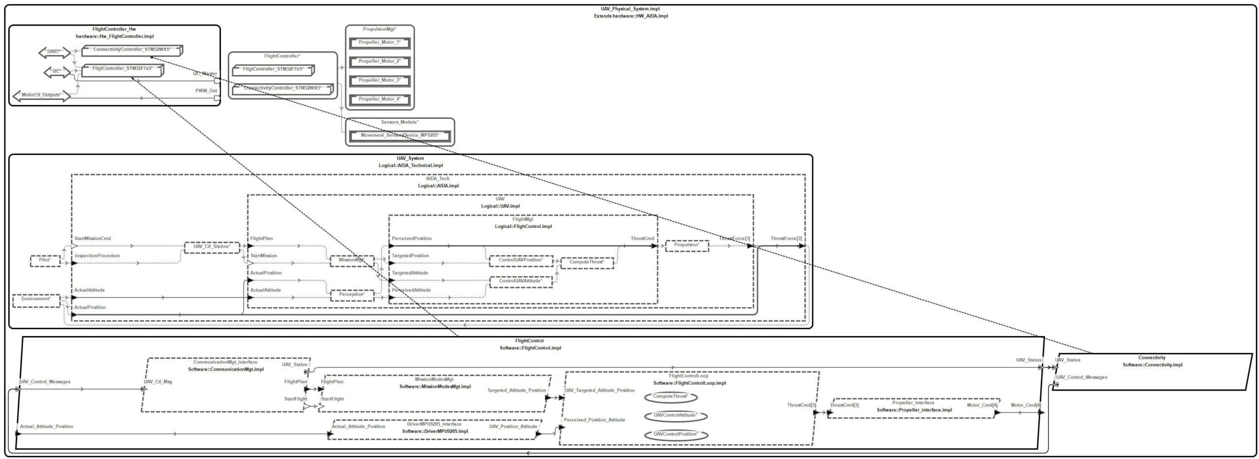
AIDA UAV Hw/Sw Architecture
Perform Timing Analysis thanks to AADL
Now, it is possible to use integrated AADL analysis (static analysis, scheduling analysis) thanks to some AADL compatible simulation tools such as AADL Inspector.
We can analyze the compliance to the expected end to end timing requirements :
And then, perform scheduling analysis with appropriate simulator to check the suitability of the technical solution parameters. Indeed, defining appropriate scheduling properties may be difficult to achieve because hardware elements have physical limits (sensors sampling time, …) and software timing properties (priorities, worst case execution time, data transmission delays, periods …) are not obvious to determine. Moreover, you may encounter feasibility issues to satisfy the allocated timing budget if the System Engineer does not have these constraints in mind.
In this example of scheduling simulation, we can observe that some deadlines are missed , which was not obvious to determine in the initial allocation phase.
Feedback in SysML
The Systems Architect has to analyse the impacts of change requests from the proposed hardware/software solutions.
In this example, the systems engineer has performed an initial allocation of functions to logical components based on his initial knowledge. Then, the Hardware / Software Design team has performed analysis of existing components, devices and software components which exist as libraries. In our case, the analysis has shown that there is a mismatch between initially expected interfaces and provided interfaces by the selected sensor device (which implements Perception Subsystem). So, Hardware/Software design team performs a proposal to change initial allocation of FuseData function from Perception Subsystem to Flight Control Management subsystem.
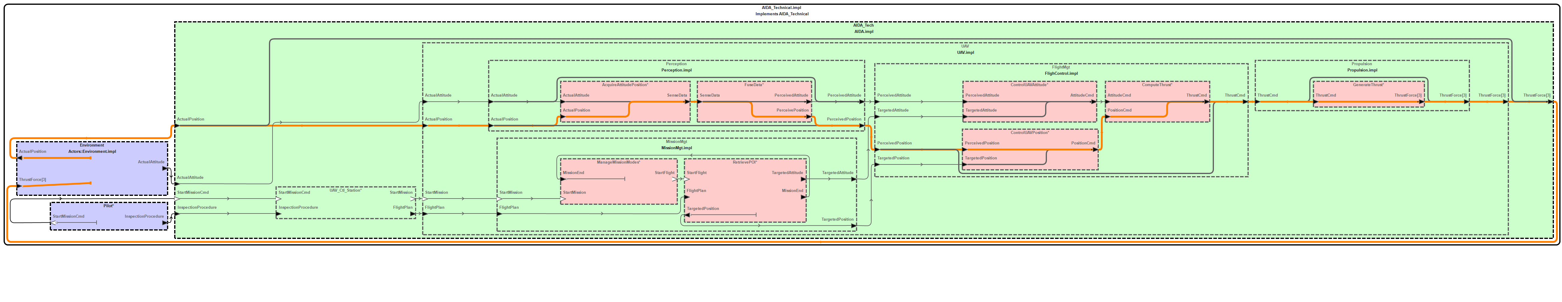
So we update the Logical Architecture in SysML accordingly, as shown in the following figure:
Modified Logical Architecture after AADL analysis.
In addition, some timing budgets between subsystems can be adjusted regarding the feasibility of the proposed solutions when possible. Some changes in timing requirements or in interface definitions may have consequences on other engineering specialities or on other components. So, this impact analysis is not always straight forward (rather iterative).
Synthesis
In this article we have proposed a coupling methodology between SysML (a Systems Engineering language) and a hardware/software design language (AADL). Note that this method can easily be tuned for other languages with similar concepts (real-time, scheduling, …) such as AUTOSAR or UML MARTE.
The proposed method includes a definition of system requirements using SysML (including end to end timing requirements with the Functional Chains concept) and an initialisation a specialised model for hardware/software architectures (and associated network topologies). This translation allows to study the definition of the detailed design in the AADL language in order to benefit from suitable concepts and various timing analysis capabilities available in AADL toolboxes.
Finally, when the virtual product can be verified against its requirements, this activity can lead to a change management loop with some updates to perform in the system definition (system requirements) with potential impacts on the SysML model.
Perspectives
To complete this present work, we will later refine the analysis of the mapping between Data Types defined at System Level and Resulting Data Types from the selected design (in particular, study the influence of selected implementation types like how to implement a Real value from system to a fixed point 32 bits data and verify the suitability of the selected implementation type regarding accuracy requirements).
In other further works, we plan to investigate how to create an initial physical architecture in SysML model by defining components libraries (ECUs, sensors, mechanical components, …), network topologies and how to convert this in AADL “world”. Then, we will propose adequate automations to perform the “bridge” from SysML to AADL based on mappings (still to refine).
We also intend to explore in more detail the other AADL language capabilities and associated annexes such as the behavioural annex (how to initiate AADL modes management from SysML behavioural description) or Error Modelling Annex (how to coordinate Systems Safety Analyses, Systems Engineering model and Safety Analyses for hardware/software design in AADL).
Enjoy MBSE !
Acknowledgements
We are warmly grateful for the support of the Ellidiss company and in particular Pierre Dissaux concerning the AADL modeling and simulation activity in the context of this article.
A special thanks to Jerôme Hugues for his advice and interesting discussions about these topics.
Next articles to come…
- November 2020 – Digital continuity between SysML and Modelica
- January 2021 – Co-simulation of SysML and other models through FMI