Part 6 – Digital continuity between SysML and Simulink
This article is part of a monthly series entitled "Advanced MBSE with SysML and other languages".
In the second set of articles, this series explains how to complete the top-level system definition model, formalized in SysML, with other modeling languages and tools, considered as more efficient to perform the system detailed design or certain kinds of system analysis. Focus is put on digital continuity with guidelines concerning coupling semantics and coupling automation between languages and tools.
In this article 6, we start from a System Definition model developed with SysML and we present an approach, which uses Simulink to define or refine part of the system's behaviour such as the control loop of the system in its environment. We discuss 2 different ways of using Simulink.
Executive Summary
Context elements
In the previous articles (part 1 to part 5), we introduced a method using the SysML notation to support the following systems engineering activities :
- Formalization of functional needs
- Refinement and definition of systems requirements
- Early validation of stakeholder’s needs using Functional Simulation
- Definition of Functional and Logical Architectures
- Optimization of Logical Architectures
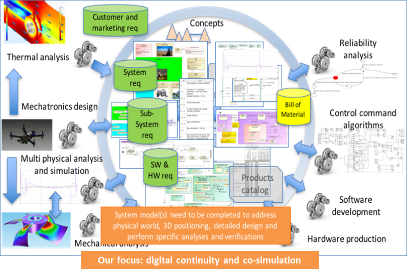
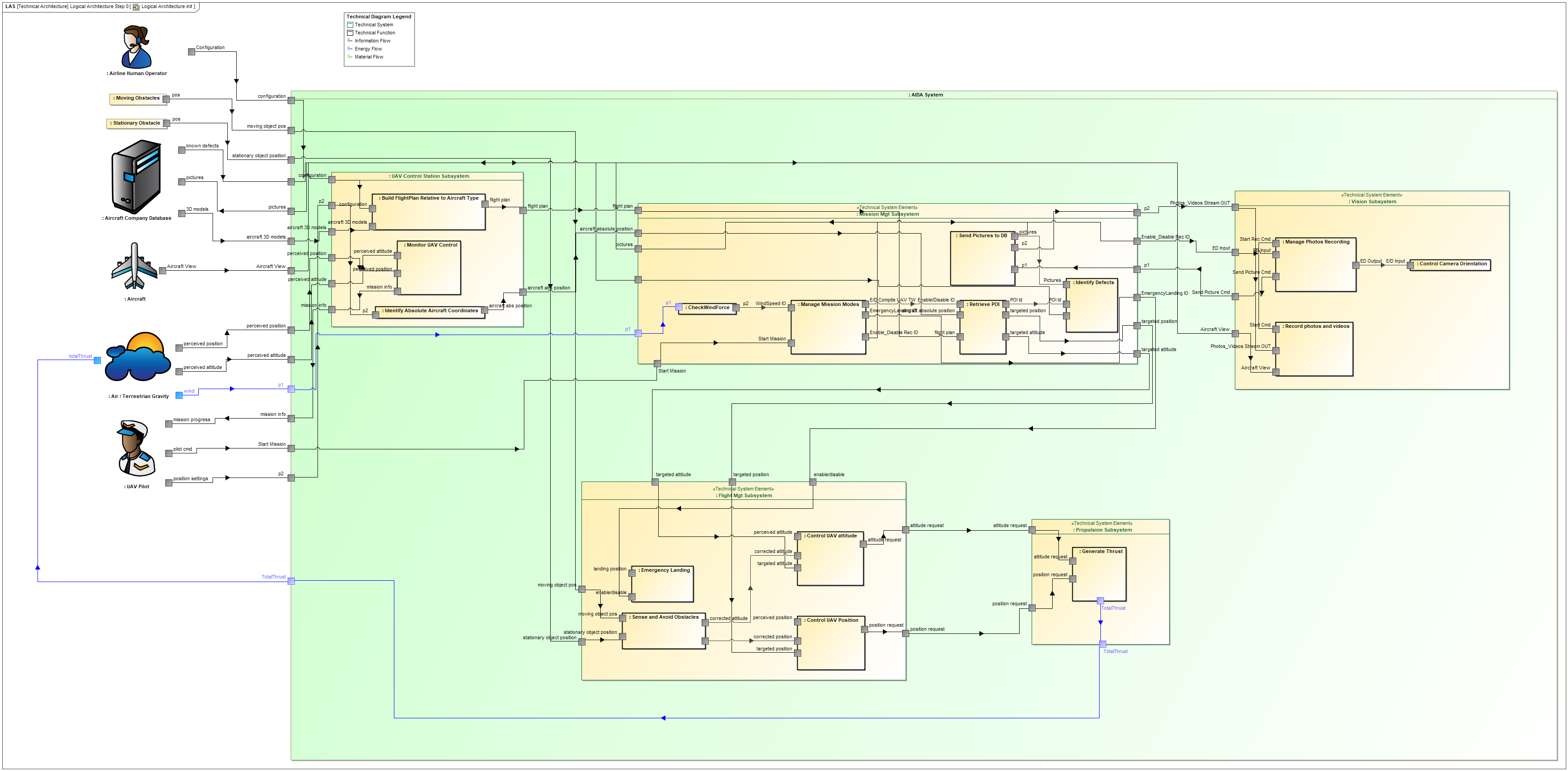
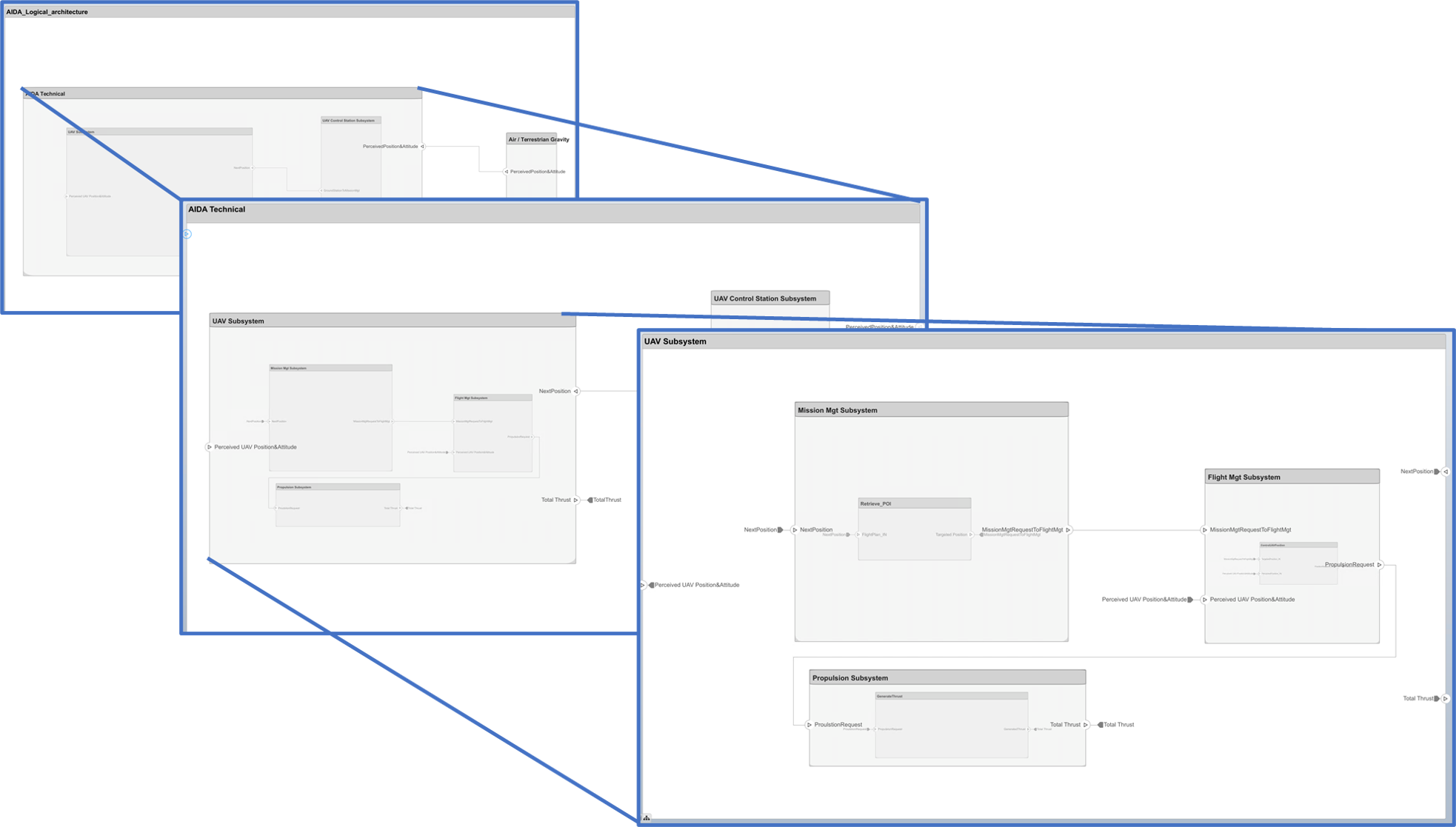
This article starts with the availability of a logical architecture for a case study called AIDA (coming from the Saint Exupery Research Institute). It is illustrated below:
From a Logical Architecture to a Detailed Definition using Simulink
Once a logical architecture has been defined, Systems Engineers start to communicate it to the various specialists involved in the system detailed definition (software engineers, mechanical engineers, command-control engineers, hardware engineers, …). These specialists will have to analyze the system requirements (including interfaces definition, expected behavior and associated performance) and will verify the requirements feasibility (is there a solution that can satisfy all of these requirements?).
In this article we focus on the Control Engineer. This specialist applies Control theory to one or several components of the system architecture and on its environment. He needs to define equations, reuse operators and generic components from libraries and toolboxes, use solvers and timed simulation, access optimization tools, use matrices based computations, etc. All these features are offered by math based simulation tools. Among these tools, we choose to restrict our focus to the usage of the MathWorks MATLAB/Simulink/System Composer suite as it is the most commonly used in the industry today, as far as we know.
Transition between SysML and MathWorks Simulink
In the next paragraph we detail a process to refine the definition of internal control. It contains the following steps:
- Definition of interface requirements in the SysML model,
- Export/translation of data to the Simulink (and SystemComposer) tool,
- Refinement of the interfaces and of the expected behavior in the Simulink model thanks to the component libraries and the support of simulation,
- Feedback to the Systems Architect about changes or refinements needed on system requirements and on the system architecture,
- Impact analysis of the change requests and update of the system definition model.
Transition from the SysML Logical Architecture to a Simulink behavioral model: the “traditional” approach
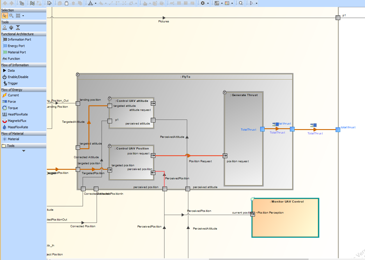
In this first approach, the Logical Architecture of the SysML model is translated into a Simulink model while preserving the allocation of system functions to logical components (subsystems). Simulink component libraries are used to refine the functional behavior. Then, the time-based simulation is used to verify that interfaces between system functions and between subsystems are consistent, and that it exists a solution that can satisfy the system functional and performance requirements. The interface definitions can be confirmed or refined by the control engineer.
Transition from the SysML Logical Architecture to a Simulink architecture model: the “new” System Composer approach
In the second approach, we still transition to Simulink but with 2 different steps and usages of Simulink. First we use System Composer (Simulink facet) to characterize and assess the architecture, thanks to features like multi-views, filtered view and analysis. Second, we use the “more traditional” Simulink component libraries to refine the function’s behavior.
The expected benefit of using the System Composer facet is a better separation of concerns: in the first step, the logical architecture can be characterized with the support of stereotypes on ports or on connectors, and assessed with the support of analysis features like “dynamic consistency checks of interfaces”. In the second step, the different components and their allocated functions can be refined, especially for the behavior, with the support of a wide diversity of generic component libraries, patterns and other useful features.
Note: each step has its own interest and may be performed by different users with different experiences.
Application on the AIDA case study
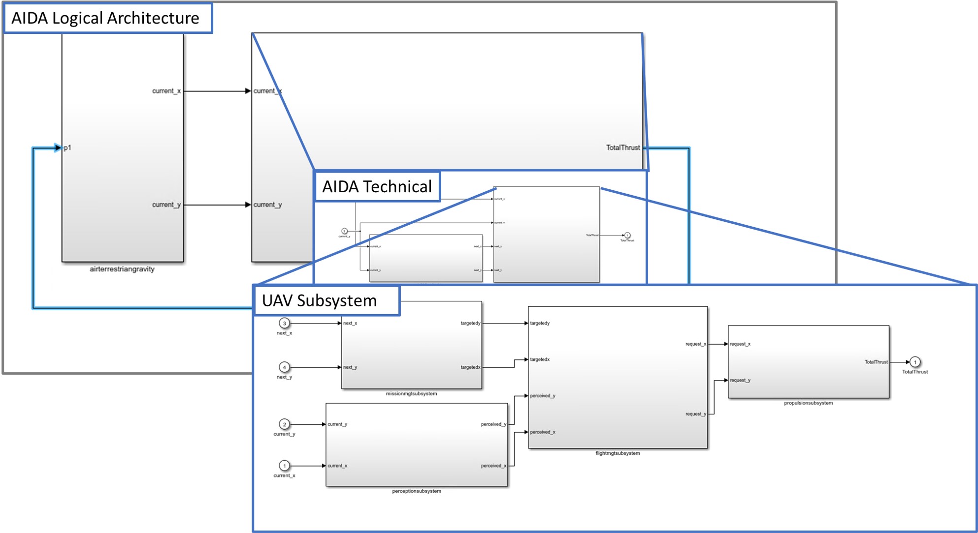
To illustrate and give elements of comparison between these 2 scenarios, we use a simplified model of control for the trajectory of an Unmanned Aerial Vehicle (UAV) based on the AIDA case study developed at the St-Exupery Research Institute. The AIDA Logical Architecture in SysML has been recalled in the context at the beginning of this article. Here we put the focus on the control loop between the perception subsystem, the Flight Management Subsystem and the Thrust Management Subsystem.
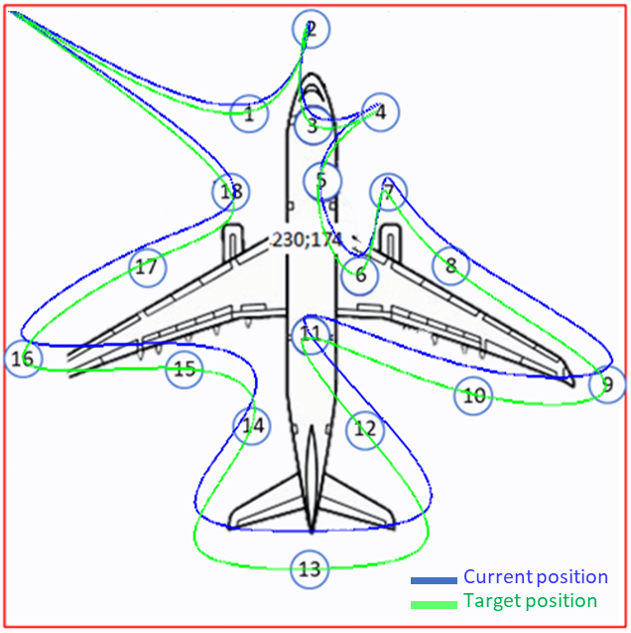
The goal is to control the actual position of the UAV to fit the expected trajectory around the aircraft. Therefore, one must find the right control parameters so that the UAV can follow the expected trajectory within a minimum error margin (that shall be defined in the performance requirements).
Simulink model initialisation
First, we define the scope of the transformation between the SysML logical architecture and the Simulink Model because we do not need to translate the full SysML model. We restrict the scope of this transformation to the sole functions and components useful for the UAV trajectory control loop (including the Air / Terrestrial Gravity model to reflect the physical environments effect on the control loop).
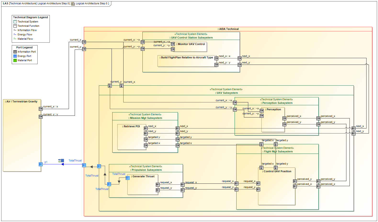
Note: in this SysML model, ports have been split (for instance current x and current y which rely on a Current Position flow) in order to be able to use the automations available in the tool.
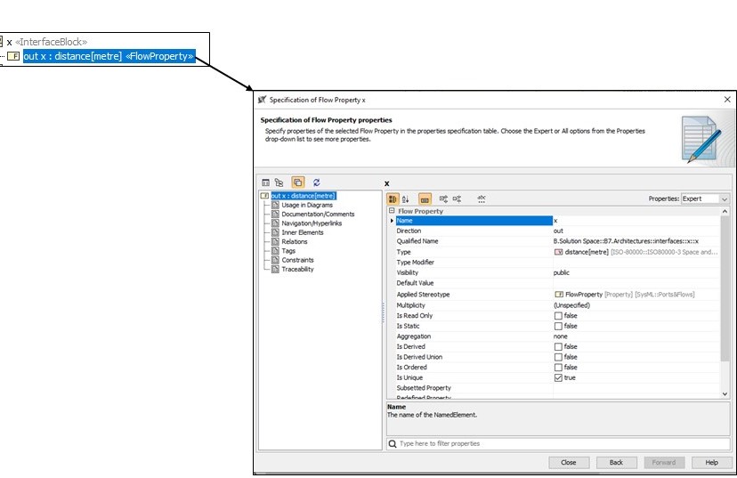
Concerning the specification of the interface types and units, the SysML tool (Cameo Systems Modeler) provides access to the ISO 80000 Standard Units :
Translation of the logical architecture from SysML to Simulink/System Composer
The SysML logical architecture can be translated to the MathWorks Simulink modeling environment through two different methods:
- With System Composer:
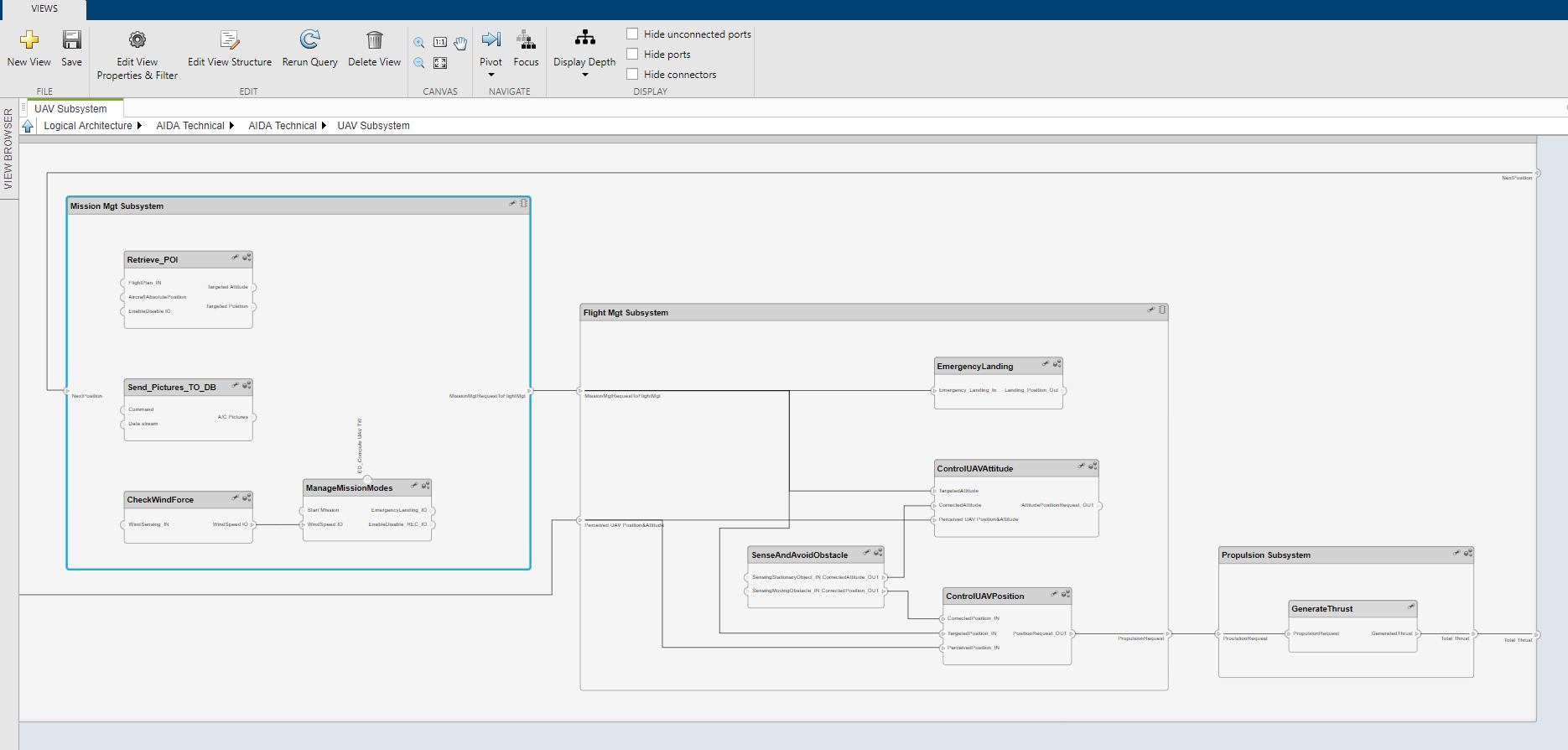
With this method, it is possible to create a logical architecture semantically equivalent to the SysML model (same components and interfaces) as illustrated below:
One of the main benefits of this approach is the preservation of the stereotypes initially defined in the SysML model. For example, in the Functional Architecture model of our case study, we have defined the following stereotypes on function inputs and outputs: Information, Energy, Material.
Within System Composer, it is possible to define the same stereotypes and apply them to the System Architecture (functions or component interfaces) :
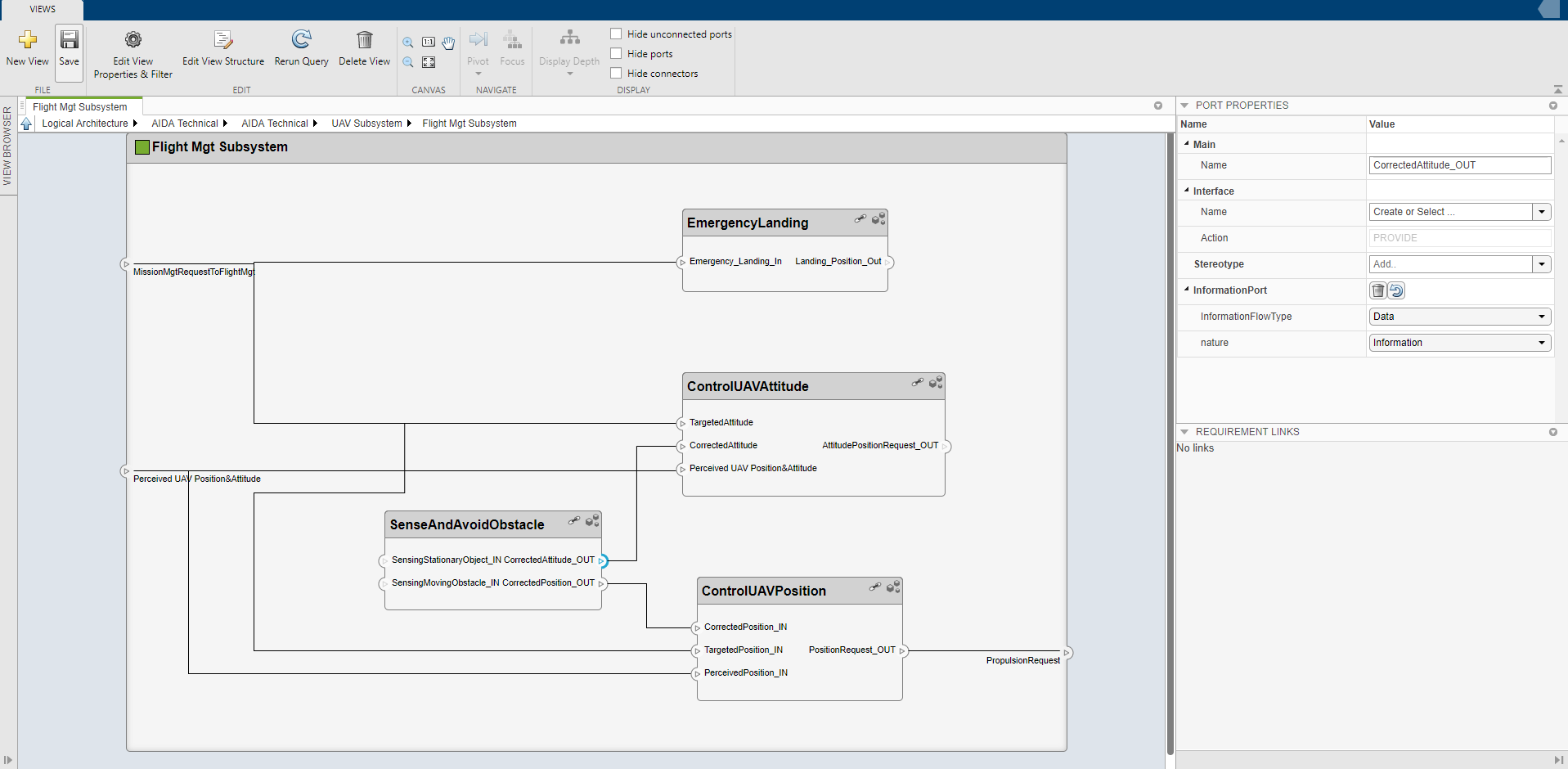
System Composer also offers a feature to filter different views of the same system architecture, which is very useful to ease the architecture reviews:
- Without System composer, using direct transition from the SysML tool to Simulink:
With this method, we can use some automations available out of the box in Cameo Systems Modeler (the SysML tool we have used) to create the Simulink Model skeleton from the SysML filtered model (model filtered with the UAV trajectory scope).
If data types and units have been specified in SysML, the automated transition propagates the data types and units in the Simulink model: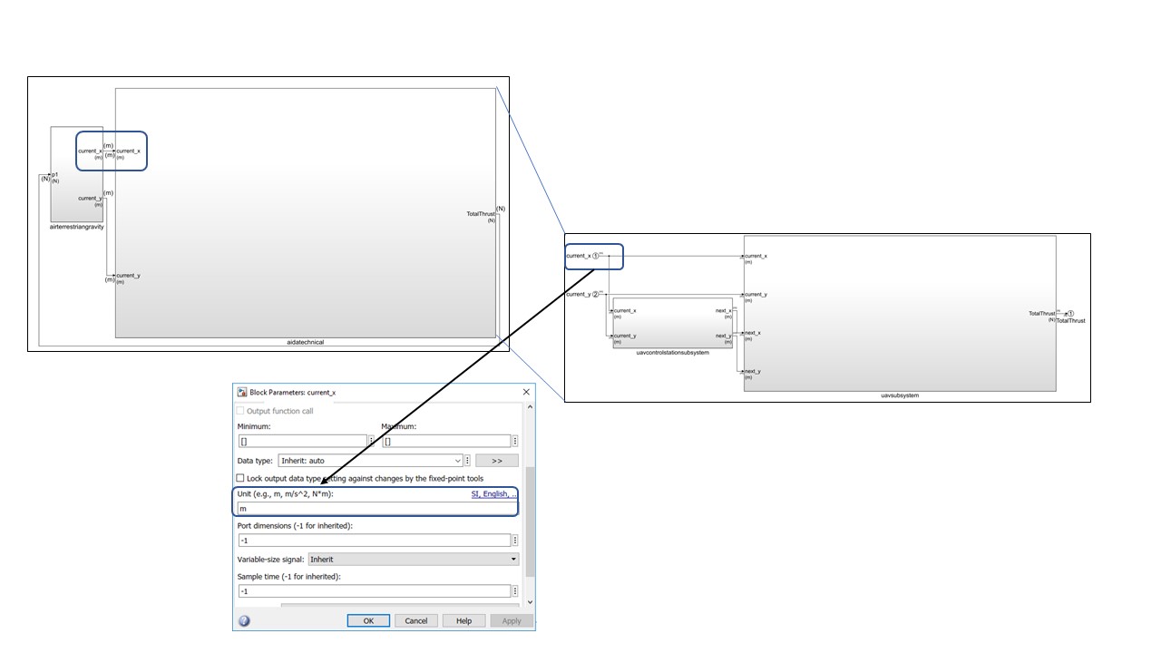
But without system composer, the additional semantics defined in the SysML model through the stereotypes are lost.
In both cases (with or without system composer), the resulting model contributes to the specification for the control engineer.
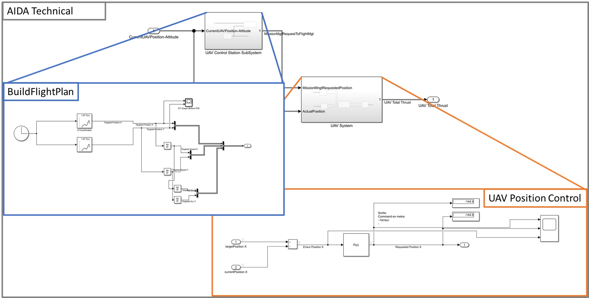
Simulink model refinement and simulation
Next, we complete the functions behavior with existing assets/knowledge in control such as PID controllers and we refine the associated parameter values thanks to the support of the simulation.
Change requests on requirements and architecture
Once the simulation seems to satisfy the requirements expressed at the logical level, it is possible to derive new lower-level requirements. For instance, it may be possible to add requirements on stability, or on expected control accuracy. The PID’s parameters can be finalized only in a physically realistic environment. However, the simulation gives an idea of the feasibility and and of the range of values to be implemented later.
Feedback in SysML
The Systems Architect has to analyse the impacts of change requests from the control engineer. Some changes in requirements or in interface definitions may have consequences on other engineering specialties or on other components. So, this impact analysis is not always straight forward.
Discussions on the two possible transitions and synthesis
This discussion is based on the use of the following tools and configurations:
- Cameo Systems Modeler (CSM) V19SP4 (SysML tool)
- MATLAB/Simulink 2020a
From SysML Logical Architecture to Simulink with the “traditional” (direct) approach
From SysML Logical Architecture to Simulink with the “System Composer” (new) approach
Synthesis
If your MBSE method is still in the definition stage, and if there is a need to go from SysML logical architecture to Simulink in order to benefit from mathematical-based simulation tools, it is clear for us that System composer is the right target from SysML. System Composer is the MathWorks tool that can preserve the SysML stereotypes put on the logical architecture (components and interfaces) and thus provides good support for architecture views and analysis in the Simulink environment. As soon as we can get some automation to support this transition between SysML and System Composer and some features to check in a static way the consistency of interfaces, we strongly recommend this way of transitioning from SysML to Simulink.
Else, in case you need to go from SysML to Simulink today, with the capabilities provided by Cameo Systems Modeler V19SP4 and MATLAB/Simulink 2020a, it is probably more efficient to use the “traditional” (direct) transition from SysML to Simulink, thanks to the automations that exist to support part of this transition.
Perspectives
In this article we have discussed the transition from a Logical Architecture formalized in SysML, to a Simulink model limited to the structure (components, their allocated functions, and their associated interfaces). Note that export from Cameo Systems Modeler to Simulink (with direct transition) also supports the translation of behavioral elements such as constraint blocks and state machines. Those aspects will be detailed in a future article.
Concerning multi-physical aspects, we plan to explore the usage of the SysPhs standard which is available in Cameo System Modeler through the SysPhsLibrary to support the automated transition of physical elements (structure and behavior) to MathWorks tools.
Additionally, we plan to explore in further detail the change analysis process that is performed when there are updates of the System Logical Architecture in the SysML model, and the possible consequences on the Simulink model. We will focus on the method but also on the tools able to support the difference/merge between SysML and Simulink models.
Finally, we will address in a future article (planned for January 2021) how to perform co-simulation between a SysML behavioral model and other behavioral models using the FMI for Co-Simulation standard.