This article concerns document generation from MBSE models. We explain why and how to use the document generation capability provided by modelling tools to get the most out of your Systems Engineering models.
We start by explaining why generating documents from your models is useful. This can seem obvious, but it is not. Next, we present the generic mechanisms behind document generation, regardless of the language, method and tool used for your model. Then we suggest a method in 3 steps to generate a document. Finally, to make things concrete, we illustrate document generation in the frame of an identical system model formalized with 2 different languages and tools, to show that we can reach the same results independently of the tool used. For this practical demonstration we have chosen two combinations of languages and tools widely known and used by the MBSE community:
- the Systems Modelling Language (SysML) in combination with the Cameo Systems Modeler tool,
- the Arcadia Language in combination with the Capella tool.
This will also demonstrate that the document generation can be done almost independently of the method chosen to model your system.
Why generate documents?
We want to use models but we still need documents…
First, let us imagine a world where everyone would be trained to read and write models just as we learn to speak natural languages. We could assume that, at some point in time, models would replace most of the documents exchanged to define, build, verify and validate a complex system.
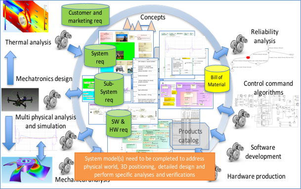
However, in the current industrial reality, this situation is not likely to occur for decades, if at all. Eventually, within the system definition team, we can assume that team members work with models and consider models as engineering artefacts, from which they are able to derive functions, requirements, components, interfaces, parameters, etc., and from which the team (the same one or a different team) can perform verification and validation. But systems engineering is far more than the isolated work of one system definition team. There are a lot of exchanges with many other teams, including:
- Capture the problem space (needs and constraints), discuss requirements, external interfaces and architecture with customers and intended users,
- Request advice, feasibility and assessment analysis on parts or the totality of the envisioned solution from domain specialists (mechanical, thermal, structure, control, safety…)
- Specify the definition of a subsystem or a component for a different team to realize it, whether in the same company or outside of it (partners and subcontractors)
- Request verification & validation of the product, at different engineering levels, from internal or external teams
- Capture the needs and constraints to industrialize and manufacture the solution
- Capture requirements from purchase/supply and legal departments when creating engagements that cross the boundaries of the company
- …
These other teams do not always understand the modelling language used by the system definition team, and they do not always need to access to the whole model. Hence, it is key to be able to extract a consistent set of model information and share it in a more commonly known language. This is where the document comes back on the scene.
Note: Here we use the term “document” in an inclusive manner to refer to different types of static media, including text, tables, drawings, etc.
For many years, Systems engineers will need to export parts of their model in document formats to allow people not trained or not trained enough in the system model notation (SysML, Arcadia or any other formalism) to understand and analyze the information contained in the model. The goal should be for the model to remain the central repository, the source of truth for all the actors of the project, with exported views adapted to the unique needs of each actor or team involved with the project.
Once we are aware that we need to share documents with other teams (and sometimes within the same team), the central question becomes:
“Shall we build those documents manually or generate them from our model?”
Just as the System Model can be the center for other different analysis tools, it can be the center for your documents, ensuring consistency between the documents relating to the system.
It is really a good idea to generate documents from a model?
This may sound like a silly question, because it seems obviously useful and time-saving to generate the documents. But document generation is long to set up and it requires a lot of effort to get familiar with the document generation approach and the associated tools. For a project with strict deadlines and a limited budget, investing in document generation is not an obvious solution.
In the short term, if the project has short and strict deadlines for the first deliveries, and if the question of generating documents has not been anticipated, the answer is quite simple: “Do not try to generate your documents from your model”. Creating a document (architecture, interface, specification, verification plan, …) will always be faster by hand the first time. You start from a template or from an existing document that stems from another project, then you copy and paste some diagrams, you extract some requirements from your requirements database, and you complete with it with some explanations and drawings. It takes time to arrange the information, time to review the document and to check the completeness and global consistency, but you know you will succeed in writing this document because you know what information to include and where to find it. If you have only just discovered document generation, you do not have any idea of the time you will need to set up everything required for the document generation to work, so it adds a lot of stress if you are short on time.
After a few iterations, as your system definition evolves, you will probably need to update your document (architecture, interfaces, …). You may realize that it becomes tedious to identify the parts of the document that must be updated and to perform those modifications. Especially if those modifications have already been performed in the system definition model. In this case, you have two repositories that share the same information: the model and the document. So now you spend time reflecting any changes in both places, with most of the effort spent to lay out the information, and with risks of inconsistencies between the two repositories. This time is not spent on engineering, but on synchronization.
After a few iterations it becomes very clear for everyone on the team that this double update is expensive and does not bring any value. This is where there is a high risk: give priority to the document…
and lose control of the model.
At Samares Engineering we have a lot of experience in using models. We know that when the project is operational, when there are strict deadlines to conform to, the pressure on the system team regularly rises to deliver some documents because those documents are contractual. Priority is given to their delivery and when time is in short supply, some changes are reflected directly and only in the documents. The synchronization between the model and the documents is not maintained. The consequence is simple: the model becomes progressively obsolete and loses most of its value because it does not reflect the current problem or solution space. The reference is now the document and no longer the model. This is the end of the value of the model. A good example of failure in MBSE. And there will be people who ask you why you spent so much time on building a model…
When looking at the long term, generating documents from the model is the only option.
You know that you cannot afford maintaining the same information in two repositories. If you really want to use models to support systems engineering, then your documents must be deduced from the model, which requires some automation: generate document(s) from the model. Now you know and can prepare your project team 😉
Which documents can we generate?
From our experience, the main kinds of documents generated from a system model concern the system architecture: list of functions, functional breakdown, functional architecture, components, Product Breakdown Structure, interfaces, functional behavior, automatons.
We also often find the description of needs and expected functionalities: use cases, context diagram, external interfaces, scenarios, some state machines, and the generation of Interface Control Documents, either as text (word documents) or as excel sheets.
Note: we can also use the document generation capabilities to extract views not defined in the model, as long as the information is included in the model. For instance, we can build tables that relate use cases and requirements with test procedures described as sequences or state machines to give metrics to the project manager on the traceability.
Some tools, like Cameo Systems Modeler, have the capability to compare two versions of a model and to generate the differences between them in a document. In this way, document generation can be a tool for analyzing the evolution of the models between 2 versions.
Finally, any information stored anywhere in the model, can be put into the generated document. The customization of templates makes it possible to adapt the generated document to the specific needs of your company, project or team.
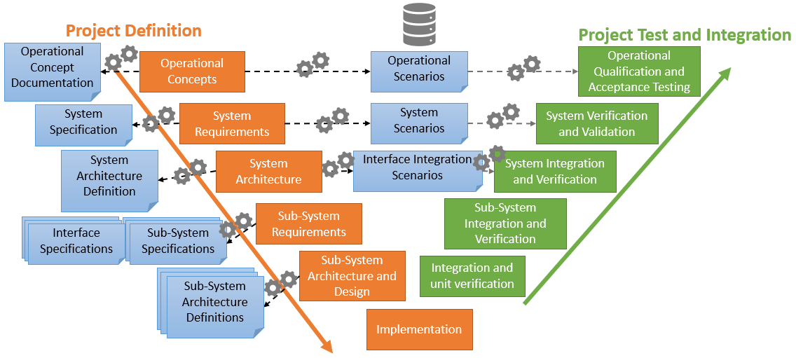
Examples of documents that may be useful to generate at different stages in the project life, represented on an example of the V-cycle.
How does generating documents work?
The ability to generate documents is not native to any modeling language, but to the tool used for the modeling. Typically, a template is written, containing queries that specify where in the model some specific information can be found, and how this information should be presented in the document. This template in combination with a model is then processed by a document generation tool, in order to produce the generated document. As mentioned in the introduction, we will focus on the modelling tools Cameo Systems Modeler and Capella, which each use a different document generation tool.
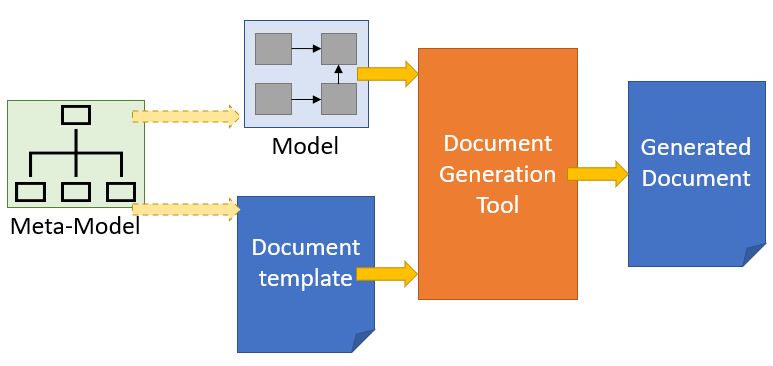
Illustration of the principle of generating documents from a model.
The principle, as illustrated in the figure above, is the same no matter the tool used. The template and the model must be constructed respecting the same metamodel, and the same modeling rules. This is the only way to ensure that the correct information can be found in the correct place in the generated document. For languages like Arcadia/Capella, that have less customization options, the same template can possibly be used across several different projects, with minimal adaptations. For languages like SysML, that are extendible by nature, and where different extensions (profiles) may exist within the same company in order to address different specific cases, the templates may require more rework in order to be reused. However, if this is known in advance, it is possible to make the template compatible with all the different extensions (profiles) from the get-go. This will require more of an effort in the beginning, but less maintenance than having several templates to maintain.
All this depends on the specific needs of your company and the different teams within your company.
Using Cameo Systems Modeler for document generation
In Cameo Systems Modeler, the document generation tool is called Report Wizard. It is a technology developed specifically for Cameo Systems Modeler and comes natively with this tool. Report Wizard is based on Velocity, a Java-based template engine. It requires templates to be written in Velocity Template Language (VTL) (Velocity User Guide).
To generate a document from a model using the Report Wizard, it is enough to open the Report Wizard from the model that the document should be generated from and selecting the desired template. Just like any other wizard, it guides the user through the steps of the documentation. Cameo Systems Modeler comes with a fairly wide selection of templates, though in order to obtain a document that is truly useful, custom templates will be necessary. However, these existing templates do give good starting points for developing custom templates.
The Velocity Template Language is written in plain text directly in the template document, where the formatting applied to the template queries (code) reflects the formatting in the finalized generation.
In VTL, each variable is prefaced with “$”, and each command line to be executed starts with “#”. Any lines of text not prefaced with “#” will be reproduced in the generated document, though any variables (starting with “$”) will be replaced with their value.
In addition to the basic queries and operations native to VTL, some helper modules and special variables have been developed specifically for use with Cameo Systems Modeler, that make some of the information in the model much easier to access. For instance, the variable $elements is a list of every single element that exists in the scope of the model selected for generation, and the helper module $report makes it possible to obtain a filtered list of elements.
For example, if your model looks like this:
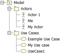
Using this template:
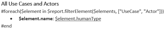
Will give this result:
VTL can be used in many different formats, including Word, Excel, PowerPoint and html. In this article, we only focus on the generation of Word documents.
Using Capella with M2Doc for document generation
Capella does not have a natively integrated document generation tool. However, since M2Doc (M2Doc reference documentation version 3.1.1) is a technology developed to work with any Eclipse Modeling Framework (EMF) -based model and Capella is based on EMF, the two are compatible. The M2Doc plugin must be installed separately, as it is not natively delivered with the Capella installation. M2Doc requires a Generation Configuration file (.genconf) to serve as the “glue” between the template file and the model. Wizards exist to guide the user in creating the Generation Configuration file and the Template file. Only one template example for use with Capella is available, developed based on the In-Flight Entertainment system (IFE) example by OBEO. This template is not likely to be useful for a company as-is, but it provides a good starting point for developing a custom template.
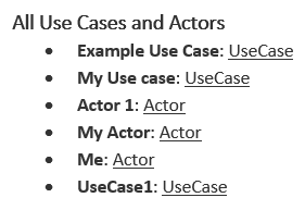
The template language used with M2Doc is the Acceleo Query Language (AQL) (AQL documentation), which in turn is based on the Object Constraints Language (OCL) (Object Constraint Language Specification Version 2.4 – omg.org). There are no Capella-specific helper modules or variables that exist, since M2Doc and AQL are generic to all EMF-based models, but in Capella there is an interpreter view that makes it possible to see the result of any AQL query immediately and thus is very helpful when writing the custom templates.
Example of the Interpreter view in Capella used to see the result of an AQL query.
In AQL, the variable name “self” is used to refer to the current object. When using the Interpreter view, “self” refers to the currently selected element, and it changes dynamically as you click on different elements. When writing the template, this works differently. You need to declare a variable in the template properties (it is possible to declare several) that will serve as the starting point for exploring the model. It is generally recommended to name this variable “self” and to set it to the System Engineering element. This element is the top-level root element, just below the .aird, and it is obligatory in all Capella models.
M2Doc is currently only developed for Word documents. The AQL queries are included in code fields within the Word template, and the formatting applied to the queries reflect the formatting of the result. Each code field starts with “m:” to signal that this code field should be interpreted by M2Doc. Standard Word code fields, such as ones used to calculate the page number or the figure number, are still compatible and should be used just like in any regular Word document.
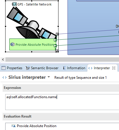
As an example, if your Capella model looks like this:
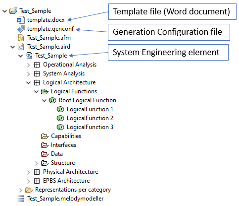
Example of a Capella model, where the template (Word) file, the Generation Configuration file and the System Engineering element are indicated.
And your template (Word) document looks like this:
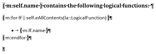
Example of M2Doc code. The variable “self” indicates the System Engineering element in the model. This code collects and lists all the Logical Functions that exists anywhere below the System Engineering element.
Then the result of the generation will look like this:
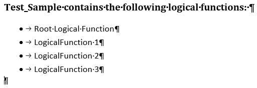
The result of the generation of the above template applied to the above model.
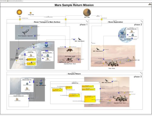
Presentation of the Use Case: UAV for Agriculture
To show off the capacities of both modelling tools, we present here the same system modelled in a similar manner using both Cameo Systems Modeler, and Capella. This system is an Unmanned Aerial Vehicle (UAV), also called drone, dedicated to treat fields against pests or illnesses. For this article, we focus on the logical architecture, with functions and requirements allocated to the logical components. We chose to focus on this layer in this article to show how to use the model to generate a preliminary specification for one or several components of your system. This specification can, once it has been completed, be provided to a sub-contractor, or to a team internal to the company, responsible for buying or making this component.
Note that we are talking about a preliminary specification. Most companies that write specifications have some sort of template to serve as a support for writing new specifications, and the exact contents of the specification will vary from company to company. However, it is common for there to be an introductory part with information about the project context for the specification, to help the reader better understand the component being specified. While some parts of this context can be included in the model (name of the global system, other components or external actors that interface with the specified component, etc.) other information such as contact information and referenced documents are rarely included in the model. While it is technically possible to include ALL the information in the model, this can make the model hard to maintain, and the system model is not necessarily adapted for this kind of information. We recommend using classic tools for all information that does not naturally belong in the system model, and completing the partially generated document by hand after it has been generated.
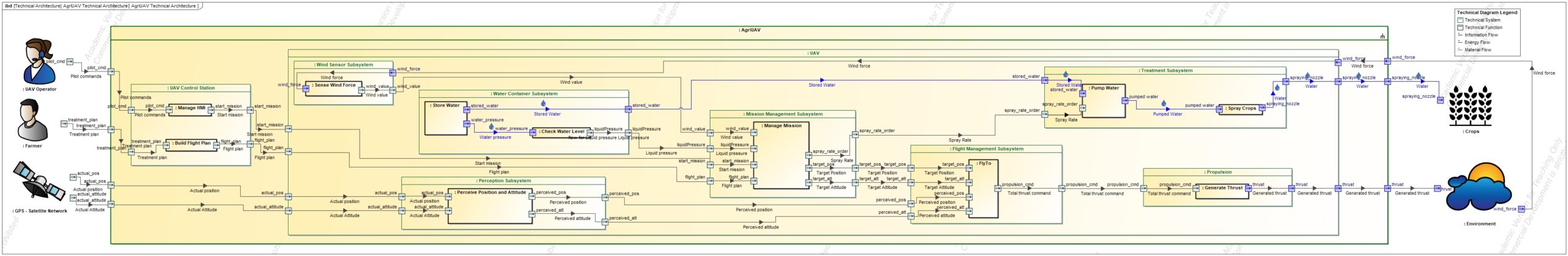
The AgriUAV technical (logical) architecture, modelled in Cameo Systems Modeler using SysML and custom stereotypes.
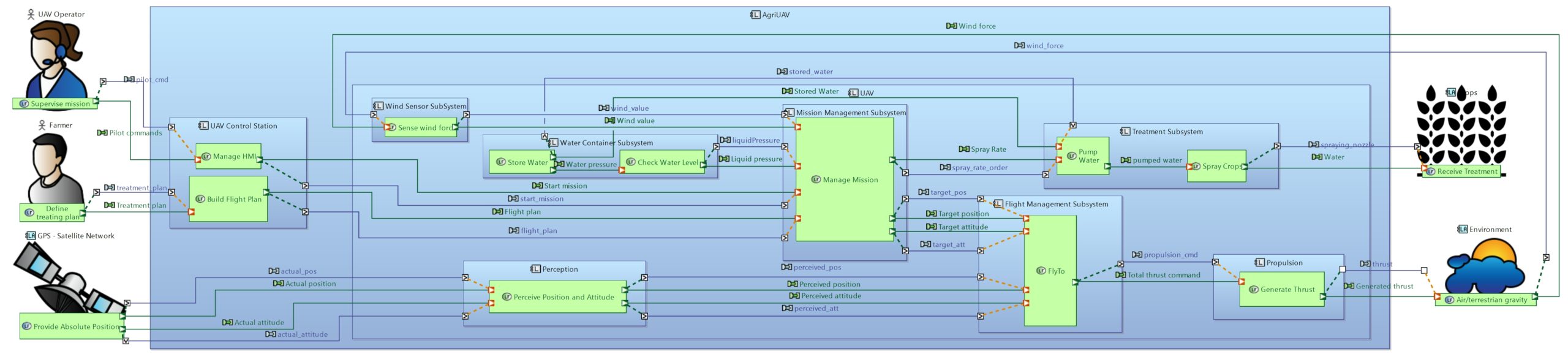
Logical Architecture of the AgriUAV modelled with Capella.
Creating the Specification document – 3 steps
We will generate a preliminary specification document from each of our models in order to illustrate one of the uses of document generation.
In the next paragraphs we present a method to setup the document generation.
Note: This method is illustrated with the specification document generation, but the method applies to any kind of document to generate.
Step 1 – Characterization of the output
The first step in the document generation setup process is figuring out what we want to display in the output document.
In our case (the system specification), most of the time the system team knows what information to include because specification documents are used in most projects and there is often a Word template defined by the company to guide systems engineers to ensure that all the key information will be filled (or marked as not applicable). This step then consists in taking the template document and using it to describe precisely what we want to display in each chapter and with which layout: list, table, image… It is a good idea to use examples of information from previous projects (modified if confidentiality applies) so that we can have a good idea of the contents and the layout of the target output document.
For documents that are less common or project-specific, where there is no pre-defined template to base the generation template on, this step will consist in identifying all the information that we want to see in the generated document and to determine the layout of this information. Examples remain useful to ensure everyone understands the same thing and agrees on the final result.
Step 2 – Map dynamic document information to model data
We can separate the contents of the generated document into two categories: static and dynamic. Static content remains the same no matter the model it is generated from, and is included in the generation template in the same way it would be included in a regular template. This content typically includes the cover page with the company information and logo, as well as (some) titles, a table for the revision history, etc. Dynamic content is content that changes based on the model it is generated from. In other words, it is any and all information obtained from the model.
In this second step, we focus on the source of the dynamic information to display in the document. We assume that the static information is already put in place in the template document based on the information obtained in step 1.
For all the different dynamic information (use cases, scenarios, context, functions, requirements, interfaces, components, traceability links….), we first have to identify if this information is present in the model. Sometimes we face a case where parts of the dynamic information we want to include is not present in the system model. For instance, in the specification document we might want to display the traceability to the customer requirements, but our system model does not contain the customer requirements. These are instead stored in a dedicated requirements database. In this example, we realize that the dynamic information we want (the traceability links to customer requirements) is not available in the system model. In this case, there are two solutions; either we complete our model to contain ALL the dynamic information required for the specification document generation, or we need to build our document from several sources (example: one model + one requirements database). This last option generally means generating a partial system specification and completing it manually after generation with the information that is missing.
In this first article about document generation, we want to keep things simple. For the rest of this article, we assume that all the required dynamic information is available in our system model.
Once you have confirmed that all the dynamic information is present in the system model, you have to identify how to access this information from the model.
Let us see an example:
- You want to display in the document a table of system requirements with some of their attributes (id, text, verification method) and with their trace (if any) to one or several of the customer requirements.
- You have identified the 2 modelling language concepts that contains this dynamic information: Requirement, and trace link.
- You need to be able to distinguish the customer requirement and the system requirements in the model and select only the “trace link” that relates system requirements to customer requirements. Let us assume here that the customer requirements are requirements contained in a package called “Customer requirements” and system requirements are stored in a package called “System requirements”. In this case, only the location in the model makes us able to differentiate the Customer requirements and the Stakeholder requirements.
Note: Alternatively, we could use a tag, a stereotype or a special attribute on the “requirement” concept to differentiate between “customer” and “system” requirements.
We see here that we need formal rules to identify the information in the model. If customer requirements exist at different places in the model and cannot be easily identified (by an attribute, a tag or a finite list of locations) the document generation cannot be automated.
The mapping of dynamic information to model data requires formal rules (also called “queries”) to identify the model data. If the rules are unclear or ambiguous, the document generation is likely to retrieve the wrong data or miss some of the data that should be included.
What kind of credit can you take from your document if you cannot trust the document generation and need to verify that the output document really contains what was expected?
Step 3 – Finalizing the template document
In this step we write out the formal rules (queries) used to obtain the dynamic information from the model. The language used for these queries depend on the document generation technology used; in our case it is VTL when generating documents from Cameo Systems Modeler, and AQL when using M2Doc to generate documents from Capella.
There are different strategies that can be applied when writing queries for the template, independently of the language used. One strategy is to write the different queries as independently as possible from each other. This strategy has the advantage of allowing the work to be distributed between different people and teams, and also makes reuse of parts of the templates easier. However, depending on the structure of your document and how the different dynamic information correlates, it is not always possible in practice.
Here are two examples of differently structured documents:
- Say you have different chapters in your document that are completely independent. In the first chapter you look only at the requirements. In the second you list all the functions in your model. In the third, you list all the components, and so on. In this case, the separation strategy is perfect; each team will get their own chapter to work on.
- However, often we want the information to be linked. Instead of listing components independently of requirements and independently of the functions, it is often more desirable to have a chapter for each component, where we get to see all the information relevant to that component; all the requirements it is traced to, all the functions it realizes, all its interfaces, and so on. In this case, all these queries are linked to the same component, and are not independent. In this case, the chapter for a component would be defined once, as one huge query, and then applied to a collection of all the components in the system.
The formatting of the final output document is also done in this step. This is because, for most template languages including both languages presented in this article, the formatting is applied directly to the query. If you want to present the information obtained from a query in a table, then you put that query in a table. If you want the result to be in bold and / or in italics, then you apply bold and / or italic formatting to the query. Since the formatting (layout) and the queries are so linked, it makes no sense to separate the two.
Sometimes the company template document addresses the presentation and provides guidelines for how the different information should be laid out. However, these rules often change when using a model to generate the document, as the model comes with diagrams that may replace some textual information.
This step can take a lot of time if not prepared in advance, especially if the reader needs the first version of the document generation of the model to get an idea of the output and then change their mind on the presentation. This is a bad practice as it leads to a lot of iterations in the document generation and makes it very sequential and time consuming.
A better practice is to discuss the presentation in step 1 with dummy data, so that this “presentation” of data can be completely specified in step 1.
Document Generation illustration with Cameo Systems Modeler and Capella
Both Cameo Systems Modeler and Capella (+ M2Doc) have similar document generation capabilities when it comes to generating Word documents. They are both able to extract diagrams and any information from the model and formatting it as paragraphs, lists, titles or tables, with any style.
We created one template for each tool, containing the same dynamic information presented in the same way with the same formatting.
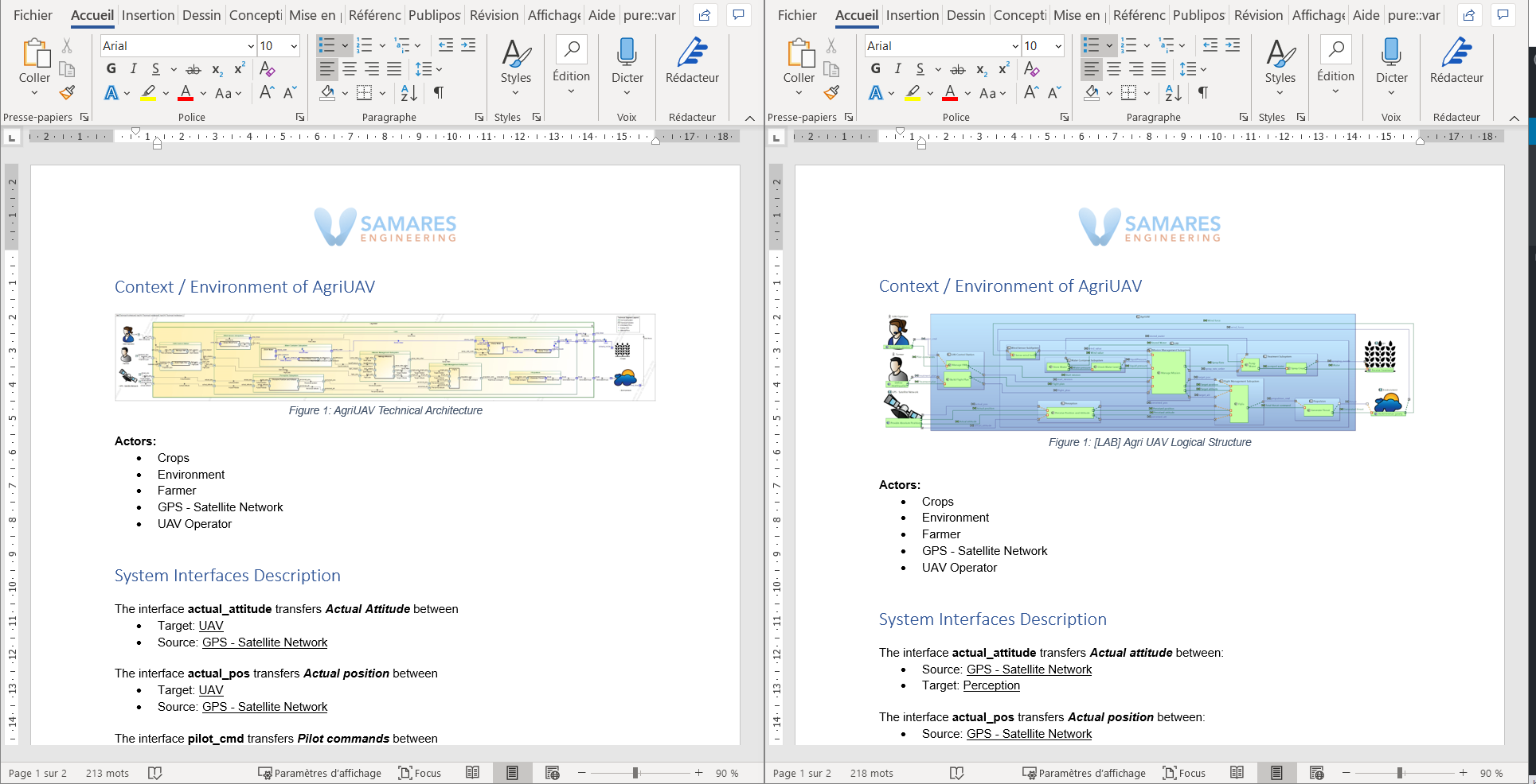
View in Word of the two generated documents side by side. On the left is the document generated from Cameo Systems Modeler, and on the right is the document generated from Capella.
In the following chapters we focus on some extracts of each of the two documents generated from the two different tools. There are some minor differences between the two documents, as we will see.
Context chapter
As an introductory chapter, we extracted the above seen diagram image, and created a list of the external actors. Except for the fact that the title of the diagram, and of course the diagram itself, is slightly different, this chapter is identical for both generated documents.
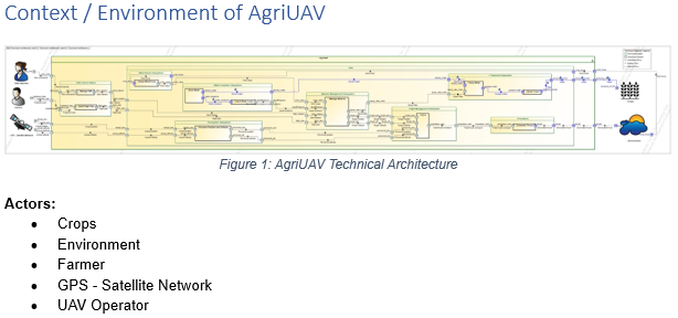
Context chapter generated from Cameo Systems Modeler.
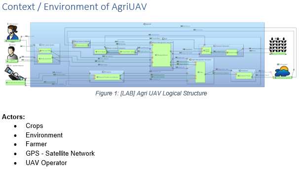
Context chapter generated from Capella.
Interfaces chapter
In this chapter we list the external interfaces of the AgriUAV (interfaces that crosses the border of the UAV), with their source, target, and the flow that they transport.
Note: This is just an example and is extremely simplified. Generally, a specification would also include information about the flow type, specific interface constraints, etc. For this article, we have decided to privilege the simplicity simply for presentation and readability purposes.
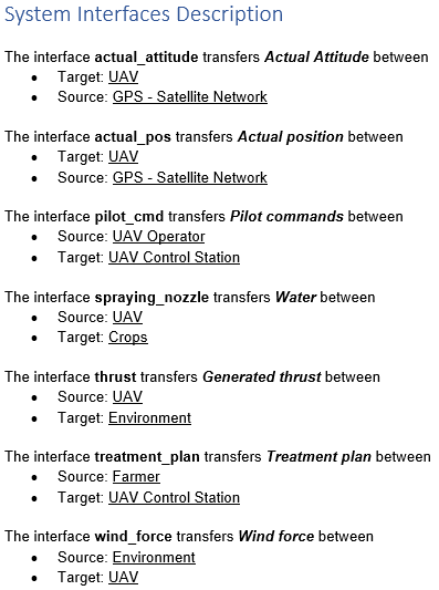
Interfaces chapter generated from Cameo Systems Modeler.
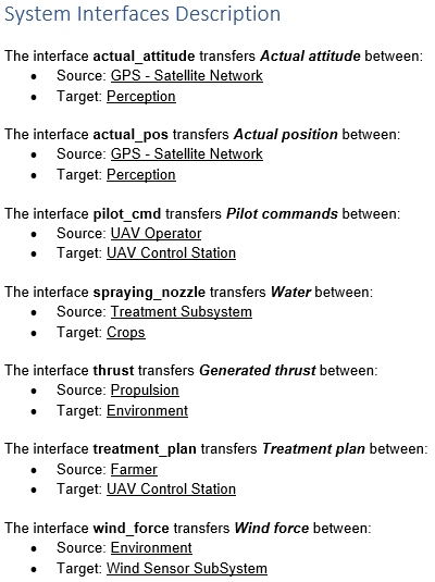
Interfaces chapter generated from Capella.
At first glance this chapter is identical, but there are some minor differences between the two due to the differences in the two modelling languages used. In SysML, the connector is direction-less; it cannot be used to determine the direction of the flow, so we have to look at the direction of the port to figure it out. For this reason, it is easier to have the “source” and the “target” in a random order (we obtain both ports and list them; an “out” port is a source and an “in” port is a target). In Capella, the component exchanges have a source and a target directly available in the properties, making it easier to obtain this information in a fixed order.
Furthermore, in SysML we have the possibility to use delegated ports, that is, a port that is not a final end but an intermediary port at the border of a block that contains other blocks. In Capella, this kind of port is calculated if we decide to hide some internal parts of a component, for instance, but it does not exist as a standalone modeling element. Because we decided to use these delegated ports in our SysML model, it is easiest to obtain just the first level of the block inside the AgriUAV, instead of the final end port, when generating from Cameo Systems Modeler, while it is easier to obtain the final end when generating from the Capella model. This is why the target for the “actual_pos” is listed as UAV in the document generated from Cameo Systems Modeler, while it is listed as “Perception” in the document generated from Capella.
We could have obtained exactly the same result for both generations, either by altering the code in the Report Wizard template used by Cameo Systems Modeler or in the M2Doc template used by Capella. We could also decide to model our connection directly from end-port to end-port in SysML, without using the delegation port, to obtain the same result as with Capella. However, for this demonstration, we found it more interesting to highlight this difference, as one solution is not necessarily better than another, and it ultimately comes down to how this information will be used.
Components chapter
This chapter lists the direct components of the AgriUAV, with their directly allocated functions and requirements. For this chapter, there are no differences between the document generated from Capella and the one generated from Cameo Systems Modeler.
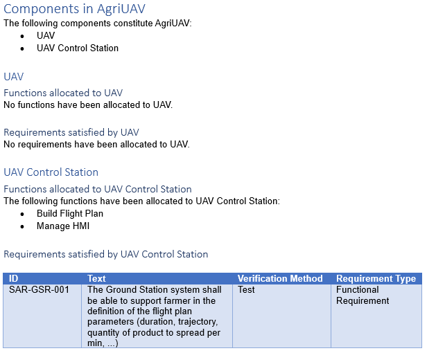
Components chapter generated from Cameo Systems Modeler

Components chapter generated from Capella.
This chapter shows that we can obtain the same structured chapter for multiple similar elements. In this case, there is a header for each component (obtained dynamically), with two sub-headers, one for allocated functions and one for allocated requirements. In this example, it is the same code that has been used in both cases (applied to a collection containing both elements), but it reacts differently if the query returns empty or not. We also see that we are able to format the obtained information as a table, if we so choose.
When looking at the three parts of this generated document, it might seem poor in terms of information. This is true; there is a lot of information we could have chosen to include, but for a demonstration in an article, we have to limit ourselves. The goal of this article is not to show what you need to include in a specification, but rather to demonstrate the capabilities of the document generation tool and inspire you to come up with your own templates!
Conclusion
As explained, document generation is a key feature when using models for systems engineering. When ready (automated), this transformation reduces the time and efforts needed to build one or several documents and allows other teams to access key up to date information about the project without needing to read the model.
However, the effort required to set up the document generation must not be underestimated, as it is not negligible. There are several steps needed to reach the first generated document, the first one consisting in determining exactly what the result of the generation should be when it is not already defined from an existing template. Document generation requires formal rules (queries) to extract information from the model and the related constraints can sometimes lead to changes in the model structure or in the way we store information in the model.
While the creation of custom templates requires some work, the result is reusable across all similar projects, which will benefit future projects (if the documents are similar).
Both Cameo Systems Modeler and Capella have good capabilities for generating Word documents and makes it possible to reach the same level of presentation (layout) in a Word document.
For beginners, adapting an existing template is generally easier than creating one from scratch, at least to understand how it works. For more experienced users, it is better to focus on reuse: templates can be improved to contain parameters and alternatives that allows the use of the same template in different contexts.
Document generation makes it possible to draw even more benefit from the model, by the vast customization possibilities that exist.
Enjoy MBSE!