This article is part of a monthly series entitled "Product Line Engineering and Model-Based Engineering".
This series explains how to combine PLE and MBSE approaches in an efficient way. Along those articles, we will illustrate different uses and benefits about product line engineering using appropriate process, methods and tools.
In this first article, we will present the concepts of Product Line Engineering and MBSE and illustrate the concepts on a Health Agriculture UAV case study using Capella and pure::variants tools.
Introduction
Currently, companies are faced with a diversity of market requirements while a lot of similarities remain between their various products. Companies are also faced with constraints to reduce the lead time to market, to provide their product to customers as quickly as possible. In order to fulfill these constraints, a lot of companies enforce the reuse of configurable components and devices to build several variants of their product while minimizing parallel development effort for products with similar aspects.
In the figure below, we illustrate this principle in the Automotive domain, where car manufacturers define a generic physical platform which is used as a “common backbone” for various car variants design.
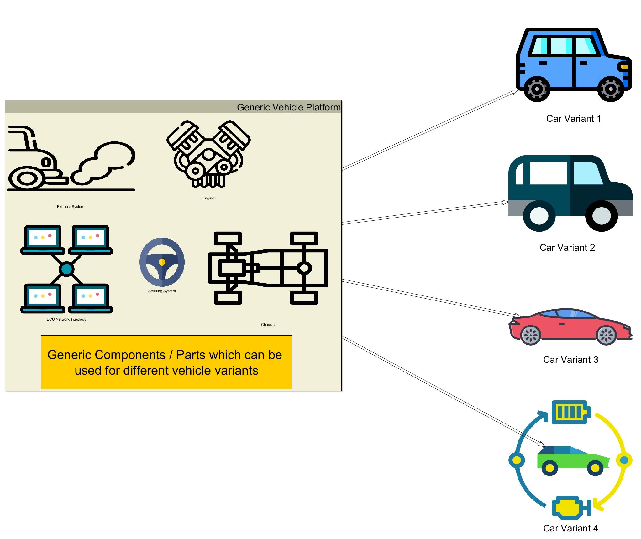
However, defining “allowed combination and parametrization” of the Generic Platform concept while ensuring the overall consistency can be difficult.
Product Line Engineering Method and tools
In order to encompass these difficulties, the Systems Engineering community has initiated the concept of Product Line Engineering which is inherited from Software Product Line Engineering practices developed by the software engineering community to generate various software artifacts according to configuration files.
In order to standardize these practices, Systems Engineering community has developed several ISO standards to describe the process of Product Line Engineering such as ISO 26550:2015, ISO26558:2017 and ISO 26580:2021.
The main concepts of Poduct Line Engineering are presented below:
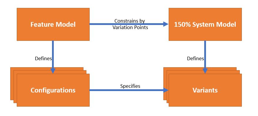
The Product Line Engineering process & method generally relies on those concepts regarding diversity :
- Feature Model : Used to define the need regarding functionalities and associated diversity.
- Configurations : Used to define the scope of different variants (which combination of features will define a specific product variant)
- 150% model: Used to define the overall model (requirements, systems engineering model, simulation models) which includes definition of all possible variants.
- Variants Models: Used to generate variant specific model, according to the configurations and the mapping done onto the 150% model.
The approach step by step is defined in the following chapters.
Definition of the Feature Model
This step consists in defining functionalities which are subject to variability in the product.
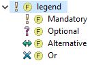
We distinguish 2 kind of features:
- Mandatory features
- Optional features
Then, for each feature, the Feature model shall define all the possible values. It shall also define the relationships between features :
- Alternatives: Only one of multiple alternative features can be selected for a specific variant
- Possibles options : tagged “OR” : options where user can select one or several features for a specific variant
Note : Additionally, it is possible to define inter-dependent features by defining the related required features or incompatibilities between features, which are not illustrated in this example.
Note: for a specific product, features can be sorted into one of the two following categories :
- Features related to functional needs or requirements
- Features related to non-functional requirements (i.e Physical architecture like Tank Size or number of propellers)
Variants description
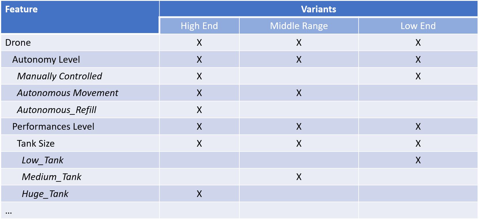
After defining the features and their relation, it is required to define the different product configurations. To perform this activity, systems engineers generally use a table to define the selected features for each variant of the product.
The table below shows a feature selection table for the Health Agriculture UAV product:
150% Architecture
Creating the System Architecture consists in building system artifacts in order to represent all the possible combinations of features for all the possible variants. It is also called a 150% model, because it contains more information than what is needed for a specific product. This is illustrated in the simplified architecture below, where you can see the three different tank sizes, even though any finished UAV will only have one tank:
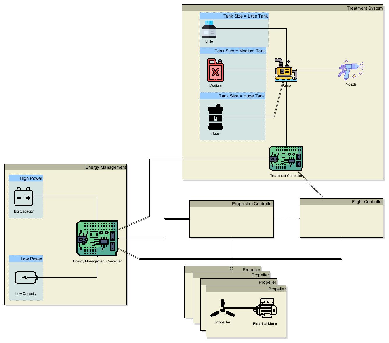
In this 150% architecture, the model reflects all possible options displayed in blue containment boxes such as High Power with high battery capacity or Low Power with low battery capacity (relation established from the constraints defined in the Feature Model).
Specific Variant architecture
Finally, it is necessary to extract the systems architecture dedicated to each variant of the project. To perform this “extraction”, it is necessary to define “variation points” in the architecture model. These variation points define the relations between the selected features and the configurable elements of the model (existence or absence of elements according to the configuration, and attribute values that change according to the feature definition). This process results in a “reduced model” concerning the selected variant (set of selected features) as illustrated below:
Note : This approach also allows to generate model elements with different parameters values according to each selected variant.
Illustration on a Health Agriculture UAV case study
Introduction to pure::variants tool
pure::variants is a software which supports product line engineering processes. It is developed by the pure::systems company and provides user functionalities to :
- define product features
- define product feature constraints (dependencies between features) with the support of an integrated solver
- define configurations (selection of features for specific variants)
- map features to external models, documents, …
- obtain “holistic” product line engineering:
- Requirements Management Tools (DOORS, Jama, Polarion, etc.…)
- Systems Engineering Tools (Magic Draw/Cameo Systems Modeler, Enterprise Architect, Rhapsody, Capella, …)
- Simulation Tools (Simulink)
- Software Engineering (AUTOSAR)
- …
Health Agriculture UAV Context
The case study concerns the usage of a Health Agriculture UAV which is used to spray a treatment product on field crops to protect them from pathogens. For this case study, we intend to develop a model of an Unmanned Aircraft Vehicle to spray the product. The main functionalities are the following:
- Prepare the Treatment Plan
- Carry and Spray product over the field crops
- Control the flight of the UAV
Health Agriculture UAV Feature Model
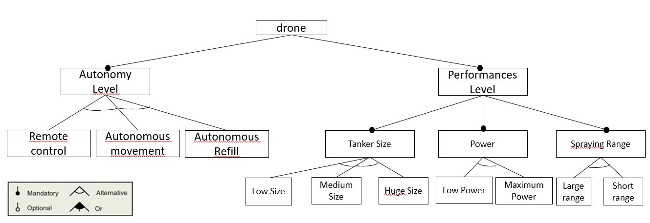
For this application, we have defined the following feature model:
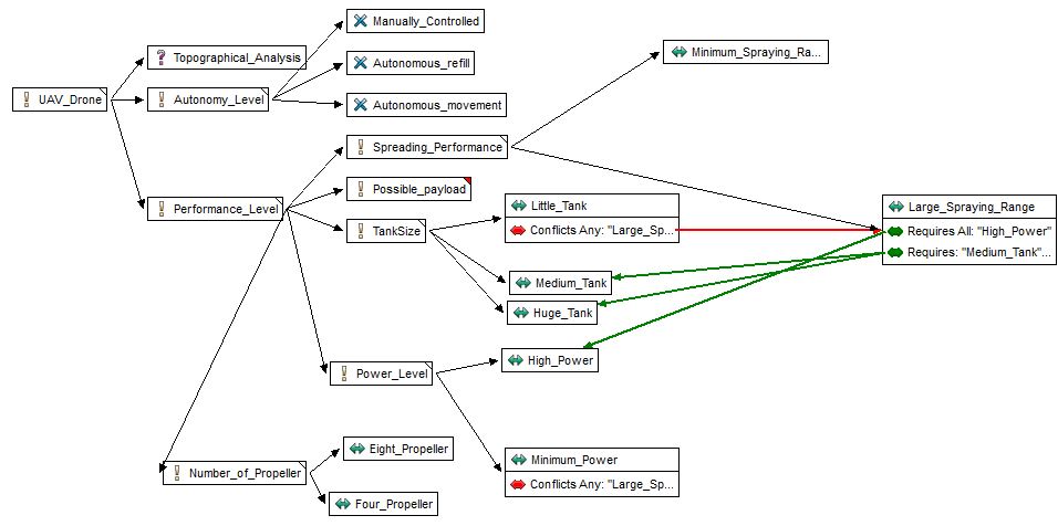
In this feature model, we have created Mandatory features, the optional feature Topographical Analysis (can be selected or not), Or Features (1..n have to be selected) (Manually_Controlled, Autonomous_Movement, Autonomous_Refill) and alternatives for the other features (exactly 1 has to be selected).
It can be noticed that we have also used “Conflicts” and “Requires” relations between features (Red and Green arrows) to model dependencies between the features.
Health Agriculture UAV Variants
After creating this Feature Model, we have defined 3 different variants of the Health Agriculture UAV:
- High End variant
- Middle Range variant
- Low Cost variant
These are defined in the matrix below:
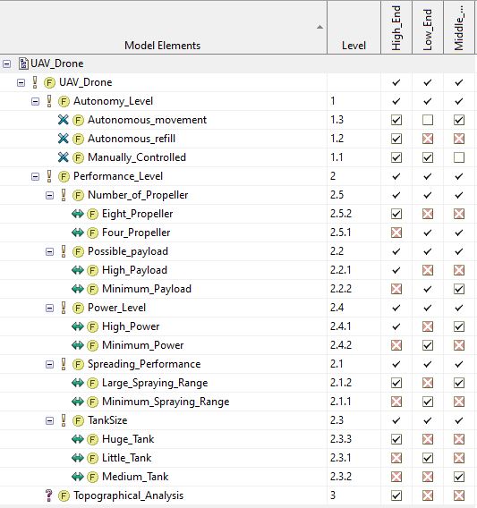
Note: The red crosses signify an impossible selection of features according to the defined constraints (dependencies and alternatives which restrict possible choices to build specific variants). The check marks without a checkbox are features that must be selected to conform to the defined constraints (mandatory features or obligatory choices based on dependencies). The check marks in a box are manual feature selections. pure::variants takes the manual selections and constraints into account to manage (calculate) the red crosses and the check marks.
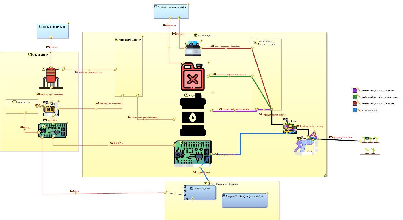
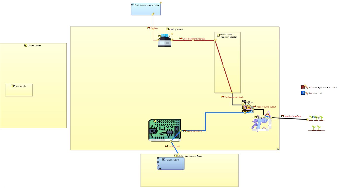
Health Agriculture UAV – 150% Capella Model
We have defined a 150% Capella model of the physical architecture of the Health Agriculture UAV model. The following diagram shows the 150% Capella model for the components which are used to implement the “Treatment System”:
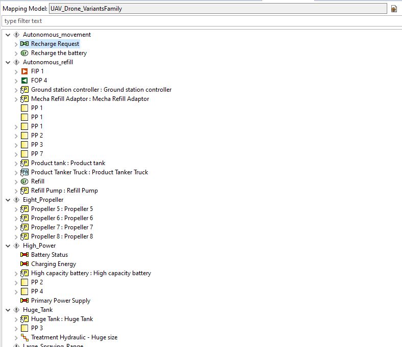
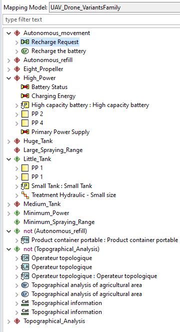
Health Agriculture UAV – Mappings between features and model elements
In order to declare the “variation points”, the pure::variants connector for EMF / Capella makes it possible to map non-common model elements to features. The following picture illustrates this functionality in the physical architecture which depends on the selection of a specific feature :
Health Agriculture UAV – Low-Cost Variant Model
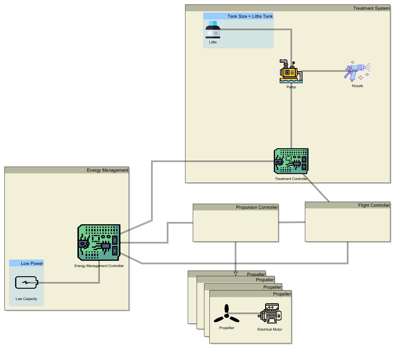
Finally, it is then possible to preview the specific variant architecture with the pure::variants connector for Capella (this will display the disabled elements as transparent) as illustrated below:
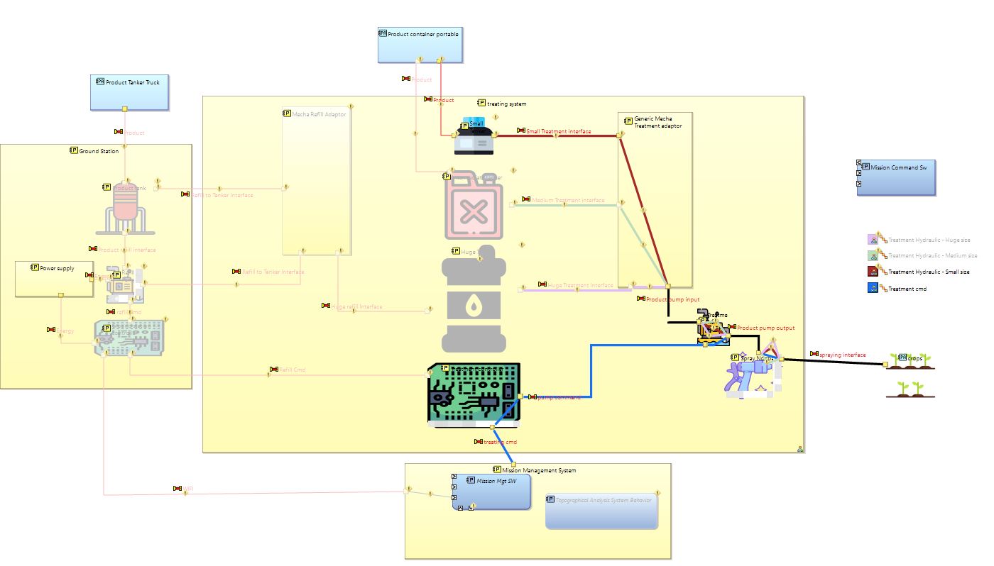
The last operation is to extract a variant specific model for Capella using pure::variants, where all the disabled elements will be removed from the resulting model:
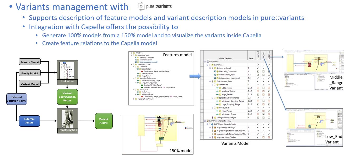
Synthesis of the approach
Conclusion and next articles
The usage of the 150% model is more or less a “chimera” which does not reflect any specific product, but all potential features included inside the whole model. A question can be raised about the efficiency and difficulty to maintain a model with such complexity.
Without using the product line management, you would have to create a dedicated model and systems engineering artefacts for each product independently. An all projects would have to manage a large part of same model elements and artefacts. It would be possible to perform reuse between those projects, but it would be time consuming to manage the various dependencies and impacts between projects during the initial definition, and when change is performed on common elements. When diversity is rising, it becomes key to benefit from product line concepts and associated tooling to support an easy creation and maintenance of the various configurations while using a unique 150% model.
In order to make this approach more efficient, companies can set up dedicated teams to support the development of generic products / component libraries, which can be parameterised to fit with different product variant expectations. In this case, the building of the physical architecture consists in defining the mapping between features (from project/customer needs) and selected products, and their associated configuration using “variation points” concept. This topic will be addressed in detail in a future article.
In addition, it is generally required at project level to include project specifics which are not intended to become generic or be part of the product line strategy. In a future article, we will address how to perform efficient co-development of project specifics and usage of the product line.
This article has presented a combined usage of product line engineering and MBSE illustrated with the pure::variants and Capella tools. In a future article of this series, we will demonstrate the usage of other tools including Cameo Systems Modeler (now called “Magic Cyber Systems Engineer” in the 3DS Catia Porfolio) and its “MBPLE” product line engineering features. We will also extend the illustration to other systems engineering artefacts such as Requirements and functions, to demonstrate the benefit of “holistic” product line engineering on a larger part of the product life cycle with the support of modelling.