This article is part of a monthly series entitled “Advanced MBSE with SysML and other languages“.
In the first set of articles, this series explains how to use a modeling approach based on the SysML notation to progressively analyze, structure, refine and derive stakeholder needs and requirements into system architecture and lower-level requirements, down to configuration items containing software and hardware parts.
In the second set of articles, this series will focus on the links to other modeling languages used to detail the design and/or perform detailed analysis and simulations to evaluate, verify or validate the virtual representation of the system.
This first article puts a spotlight on the top-level part of the V Cycle, concerning the translation of stakeholder needs into system requirements. We show how it is possible to use a modeling approach to structure and refine functional needs expressed by the stakeholders of our System of Interest (SoI) and then deduce top-level functions and draft system functional requirements.
We need different views
For the capture, structure, and synthesis of functional needs, we suggest using the following different views:
- Use Cases view, to define system missions captured from stakeholder needs
- Operational scenarios view, to show system interactions and expected reactions of the system
- System context view, to synthesize all external functional interfaces
- Top-level functions view, to list all the functions derived from operational scenarios or already allocated to the SoI by an enclosing system
- Operational modes view, that provides boundaries for activation and deactivation of functions
- Allocation matrix of functions on modes to specify the validity scope of the functions
Note: there exists other views useful to capture and structure nonfunctional requirements like Measures of Effectiveness (MoE) and physical constraints. In this article we only focus on the functional needs.
Now we will show how to use SysML to support those different views, but first we introduce the sample case that is used to illustrate the mappings: the AIDA model. AIDA is an open source model defined at St Exupery Research Institute (Toulouse, France) to formalize a drone in charge of aircraft inspection. It was initially developed with Capella. Here we have translated this example to the SysML notation. The drone used for inspection is our System of Interest (SoI) and the aircraft inspection is the main mission the drone contributes to.
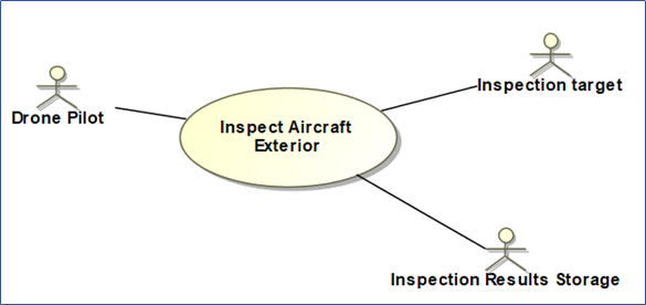
When using SysML, the Use Cases view directly maps to the Use Cases Diagram (UCD). We use the actors as roles played by external entities that interact with our drone.
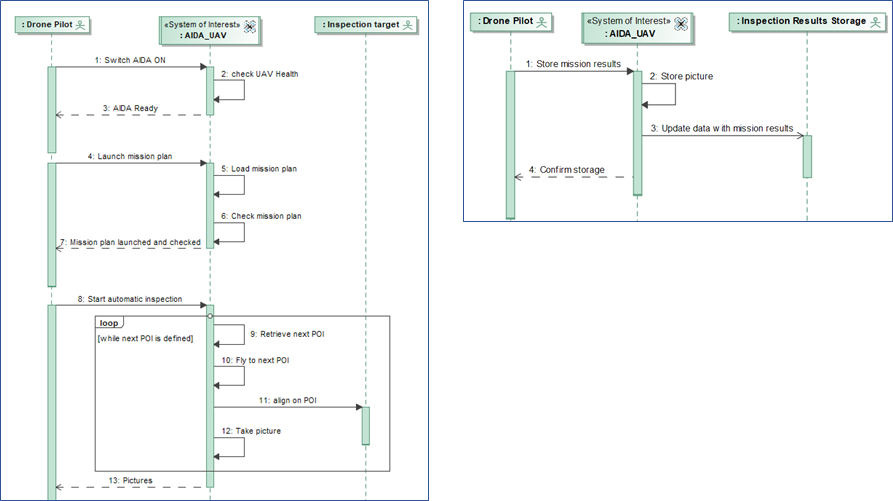
The operational scenarios can be formalized in SysML with interaction diagrams, graphically represented by Sequence Diagrams (SD). We define simple, black-box sequence diagrams showing interactions between main actor (our drone pilot) , the SoI, and the other actors that represent roles played by external entities involved in the scenario. There is no need for other lifelines.
We define as many diagrams as needed to translate all the functional needs of the different stakeholders, including our customers and users. The main goal of these diagrams is not to define the execution logic, but rather to identify the required service functions (functions that provide services to the system end-users) expected by the end-users and customers of the future system. Let us illustrate with 2 sequence diagrams:
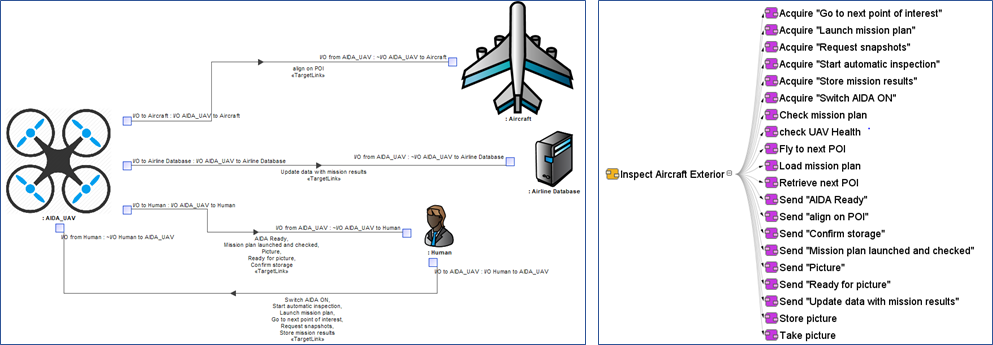
The system context view is focused on external functional interfaces. We create this view with SysML by using an Internal Block Diagram (IBD) that shows the system connected to its environment/context. By environment we mean here its physical context with the other systems or external entities that interact with our system of interest. The top-level service functions view can be shown as a tree.
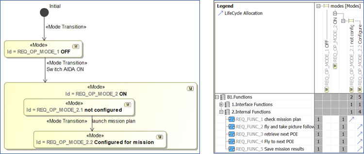
Finally, the operational modes view can be formalized through a SysML state machine. We use a “mode” stereotype to distinguish those modes from other system states. An allocation matrix is used to define which functions are available in which mode.
But these different views are not independent !
If you create these views independently, you will soon discover that there are several modeling elements that relate to the same concept. You will then realize that your model contains duplicates of the same information, with the possibility of inconsistencies…
How can we avoid this issue? By studying the links between the elements and by providing some rules for the organization of the data in the model (parent / child, owner / owned, whole / part…).
Here is our suggestion:
- Define your scenarios as behaviors of your use cases. Then you can check that your scenarios use same actors (at least a subset) of the ones associated with your Use case. You can then store your scenarios below the UC as “owned behaviors” and navigation from UC to scenarios is immediate.
- Initiate and maintain your system context (IBD) external interfaces with messages from the scenarios (at least the messages that go in or out of the SoI). Note: for this you need to map your actors to the elements of your context to enable this mapping of messages to the context elements.
- Initiate and maintain a list of top-level required functions identified from the scenario messages: external messages will lead to interface functions while reflexive messages on the SoI will lead to system internal functions.
- Identify modes of your system by looking at the mission profile (stages) and the human interaction steps. This identification is not easy and will probably lead to additional guidance in a future article dedicated to this kid of identification.
- Once you have both top-level functions and modes, you should allocate functions on modes to specify the validity of the functions validity in accordance with the modes.
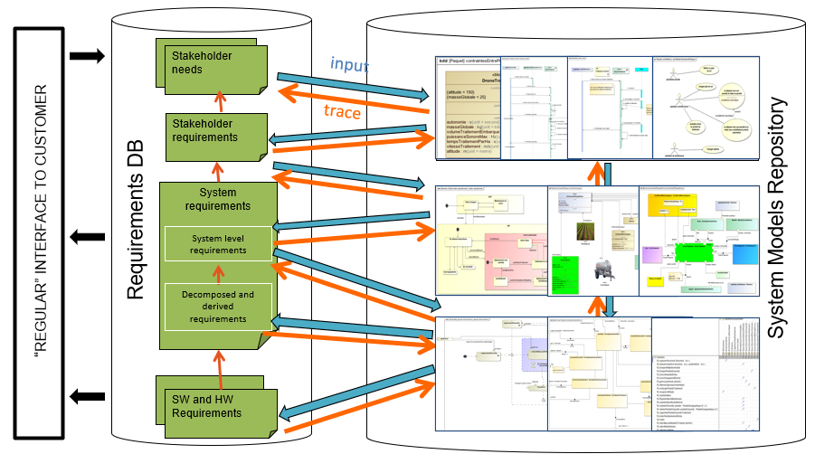
Here is below an illustrated summary of the mappings that can be made to check and ensure the consistency between the different views:
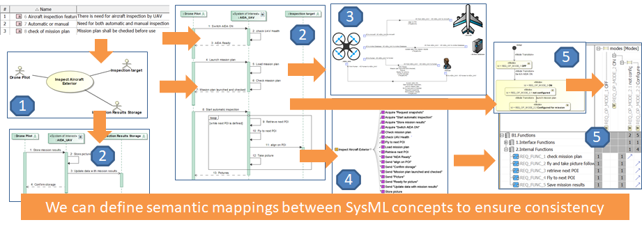
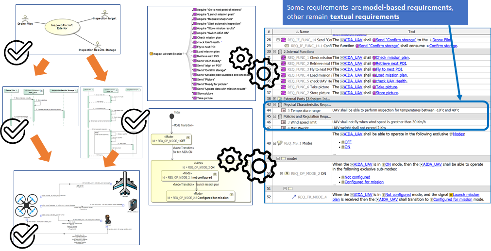
Note: when all the semantic mappings have been defined, all the views contribute to the validation of needs or the elaboration of draft functional requirements.
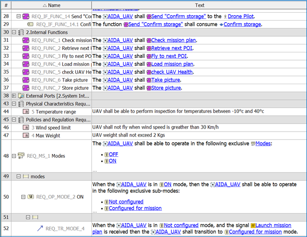
Note: in a future article we will see how these functional requirements can be completed smoothly with additional conditions, performance, and elements of verification to improve their maturity and reach good quality.
Can we automate these mappings?
Yes we can. And we did it.
We have created a plugin to automate the transformations between the views according to changes done by systems engineers. This is a “live mode”: any change in one Sequence Diagram is immediately reflected in the other views (context, functions…) including the requirements view (agile approach).
Automations in practice (video)
Look at the video to see these automations in practice. Enjoy MBSE !
Next articles to come…
- May 2020 – Derivation of requirements from models: From DOORS to SysML to DOORS again
- June 2020 – Early validation of stakeholder needs through simulation
- July 2020 -Consistency between functional and logical architectures
- August 2020 – Minimization of the coupling in the logical architecture
- September 2020 – Digital continuity between SysML and Simulink
- October 2020 – Digital continuity between SysML and AADL
- November 2020 – Digital continuity between SysML and Modelica
- December 2020 – Co-simulation of SysML and other models through FMI
Leave A Comment
You must be logged in to post a comment.