This article is part of a monthly series entitled “Advanced MBSE with SysML and other languages“.
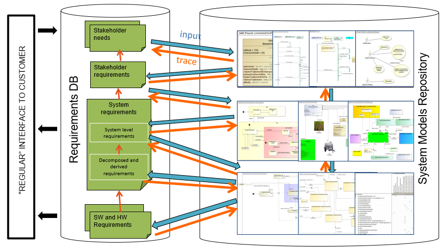
In the first set of articles, this series explains how to use a modeling approach based on the SysML notation to progressively analyze, structure, refine and derive stakeholder needs and requirements into system architectures and lower-level requirements, down to configuration items containing software and hardware parts.
In the second set of articles, this series will focus on the links to other modeling languages used to detail the design and/or perform detailed analysis and simulations to evaluate, verify or validate the virtual representation of the system.
This fourth article deals with functional and logical architectures. We discuss the following questions: Why do we need a logical architecture? And how do we ensure the consistency between the functional and logical architecture?
Why do we need a logical architecture?
In most industrial practices, and in various industrial domains, systems engineers are used to define one (and sometimes several) functional architecture(s). This architecture formalizes an arrangement of system functions using two viewpoints: the Functional Breakdown Structure (FBS), which shows the decomposition hierarchy as a tree ( “parent” functions and “child” functions) and the connection graph that shows the functional flows between those functions (energy, information, matter).
As an illustration, let us take the AIDA open-source sample case from the Saint Exupery Technological Research Institute in Toulouse: https://sahara.irt-saintexupery.com/AIDA/AIDAArchitecture.
AIDA stands for “Aircrat Inspection by Drone Assistant”. AIDA provides assistance during the inspection of an aircraft before flights: the drone seeks for Aircraft defects.
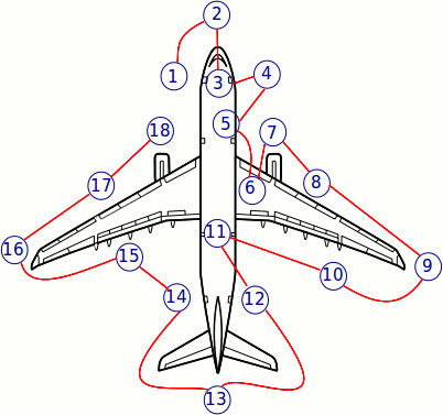
The drone system contains 9 top-level functions:
- Manage mission
- Build fight plan relative to aircraft type
- Fly to
- Retrieve PoI (Points of Interest)
- Make and record videos
- Check wind force
- Monitor UAV control
- Sense and avoid obstacles
- Emergency landing
The definition of these functions is formalized with Blocks in SysML.
We use an IBD to formalize the functional architecture. Practically, this diagram displays the usage of the functions in their operational context (SysML part properties typed by the previously mentioned blocks), the interfaces (connectors with item flows) between the SOI and the other members of the system context, and the interfaces between usages of functions (also connectors with item flows).
A possible functional architecture for the identified top-level functions is provided below:

Some of the top-level functions are still complex and need to be refined through lower-level functions. So we can build a functional architecture that displays several levels of functions as illustrated below:

When developing a system, it is also common to find a description of the physical components. By “physical components”, we mean a hardware part, a Software piece, or any combination of those elements. It includes processors, sensors, structure, propellers, etc.
The problem comes when we want to allocate our functions to the physical components. In the frame of a complex system, the list of physical components may become very large, especially when this list is not finalized and contains many alternatives. For instance, in order to allocate the “sense wind” function, we may find a lot of different technologies and means to perform the measurement, mixing software and hardware features.
As the final physical architecture shall satisfy all non-functional requirements including reliability and availability, we generally introduce redundancy of safety-critical components to ensure its availability even when there are failures in one of the components. In the end, the number of physical elements to consider for allocation is huge.
Let us take the previous example to illustrate a non exhaustive list of physical components:

The allocation of top-level functions, identified from the needs expressed by the customer and users are hard to allocate to the identified physical components because the abstraction gap between the system functions and the physical components is high. We need an intermediate layer to partition functions into items that represent an abstraction of the final technologies. This is the “logical architecture” layer.
The logical architecture as an intermediate layer
As stated by the INCOSE Systems Engineering Handbook (4 ed.), the logical architecture definition consists in decomposing and partitioning the system into logical elements
[…]. The elements interact to satisfy system requirements and capture systrem functionality. Having a logical architecture mitigates the impact of requirements and technology changes on system design.
The logical architecture is an arrangement of “logical components” that perform the functions. This first allocation is easier to perform because we can group functions with criteria such as cohesion, coupling, design for change, reliability, and performance.
Later, we will have to do a second allocation: allocate logical components on physical components (with technology). This second step is also easier to perform than the direct allocation from functions to physical components because we only have to focus on technologies/products available on the market to satisfy a logical component already defined.
Let’s go back to our AIDA example. Here is a possible set of logical components for our system of interest surrounded by its environment (as in the functional architecture):
- Mission management subsystem
- Propulsion subsystem
- Flight management subsystem
- Vision Subsystem

Here is an example with the use of the SysML allocation matrix (within Cameo Systems Modeller environment) to create the allocations of functions to logical subsystems.

How do we create the logical architecture?
When creating a logical architecture, it is possible to connect the logical components directly in the diagram, by using engineering knowledge: it is sometimes already known that 2 components will exchange information or energy. However, the rationale for connecting the 2 components is missing. In the end, the logical architecture may miss interfaces or contain useless interfaces.
Therefore, the logical interfaces shall not be fully independent of the functional interfaces. The logical components reflect the partition of functions and should thus reflect the functional flows. There is a consistency between the functional architecture and the logical architecture.
The next chapter explains this in detail.
Consistency between the Functional architecture and the logical architecture
We return to the AIDA sample case to illustrate this consistency with a few functions and allocations. Instead of looking at the full functional architecture, we will focus on a simple extract with only 3 leaf functions coming from the “manage and record videos” top-level system function:
- “Manage Photos Recording”,
- “Control Camera Orientation”
- “Record Photos and Videos”

Now we want to allocate the 2 first leaf functions to “Mission Management Subsystem” (in blue) and allocate “Record Photos and videos” to “Vision Subsystem” (in red) as illustrated below:

Note: in SysML, we use the SysML allocation matrix to edit (create and delete) these “allocation” relations. The allocation described above leads to the following matrix.

Now we would like to reflect the impact of these allocations on the logical architecture. Practically this means:
- Display the functions inside their components
- Display the functional flows between functions through the ports of the logical components because we want to respect the “encapsulation principle” of the components (a component can show or not show its internal structure but its ports do not change)
- Display the functional flows with the system environment (through the System external ports)
In our example, for the subset of the functional architecture and the 3 allocations, it results in the following logical architecture with the creation of 3 logical flows (in orange):

We can see that the logical flows (in orange) directly come from the functional architecture: they are deduced / reflected from this functional architecture and from the allocation of functions to the logical components.
Conclusion
There exist a relation between the functional architecture and the logical architecture. A logical subsystem can produce or consume flows if there is one or several functions allocated to it. In addition, some functions may appear directly at the logical layer, e.g., interface function between subsystems, encoding functions, decoding functions, or electrical functions. These functions may make no sense at the functional system level since they depend on the chosen technologies and can be very detailed. But, whatever the abstraction level of the functions, the logical layer shall be consistent with the system functional layer.
Can we automate some of the steps presented above?
Yes !
Overview of the automation
At Samares Engineering, we have created a plugin to automate the update of the logical architecture (display of functions, creation of logical flows) according to the functional architecture and allocation of functions to the logical components. This propagation is done in real-time. And it works in both directions (creation and deletion of allocations, leading potentially to the creation or deletion of logical flows between logical components). So we can ensure that the logical architecture is always consistent with the functional architecture.
We can also show the functions inside each component or hide those functions and only show the components and their logical flows.
Take a look at the video below to see this automation in practice.
Simulation in practice (video)
This video shows how we can ensure consistency between a functional architecture and a logical architecture while editing the allocation of functions to the components, in real-time.
Enjoy MBSE!
Next articles to come…
- August 2020 – Minimization of the coupling in the logical architecture
- September 2020 – Digital continuity between SysML and Simulink
- October 2020 – Digital continuity between SysML and AADL
- November 2020 – Digital continuity between SysML and Modelica
- January 2021 – Co-simulation of SysML and other models through FMI
Previous articles in the series
- April 2020 – Formalization of functional requirements
- May 2020 – Derivation of requirements from models: From DOORS to SysML to DOORS again
- June 2020 – Early validation of stakeholder needs through simulation
Leave A Comment
You must be logged in to post a comment.