Part 8 – Digital continuity between SysML and Modelica
This article is part of a monthly series entitled “Advanced MBSE with SysML and other languages“.
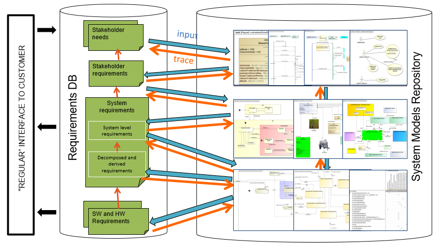
In the second set of articles, this series explains how to complete the top-level system definition model, formalized in SysML, with other modeling languages and tools, considered as more efficient to perform the system detailed design or certain kinds of system analysis. The focus is put on digital continuity with guidelines concerning coupling semantics and coupling automation between languages and tools.
In this article 8, we present an approach to refine the system definition into a multi-physical specialized architecture with the support of the Modelica language and associated toolbox.
Executive Summary
Context
In the previous articles (part 1 to part 5), we introduced a method based on the SysML notation to support the following systems engineering activities :
- Formalization of functional needs
- Refinement and definition of systems requirements
- Early validation of stakeholder’s needs using Functional Simulation
- Definition of Functional and Logical Architectures
- Optimization of Logical Architectures
SysML focuses on abstraction, requirements, functional decomposition, systems decomposition, allocation, and traceability. Within SysML, and especially in its implementation with Cameo Systems Modeler, it is possible to perform simulation and animation of state machines, activity diagrams, IBDs, or sequence diagrams, and evaluation of parametric diagrams. So, we will show that we can complete the SysML definition with Modelica concepts and use the Modelica toolbox to perform analysis and assessment of the architecture, refine our knowledge and the system specification.
This article starts with the availability of a UAV logical architecture for the agricultural domain . It is illustrated below:
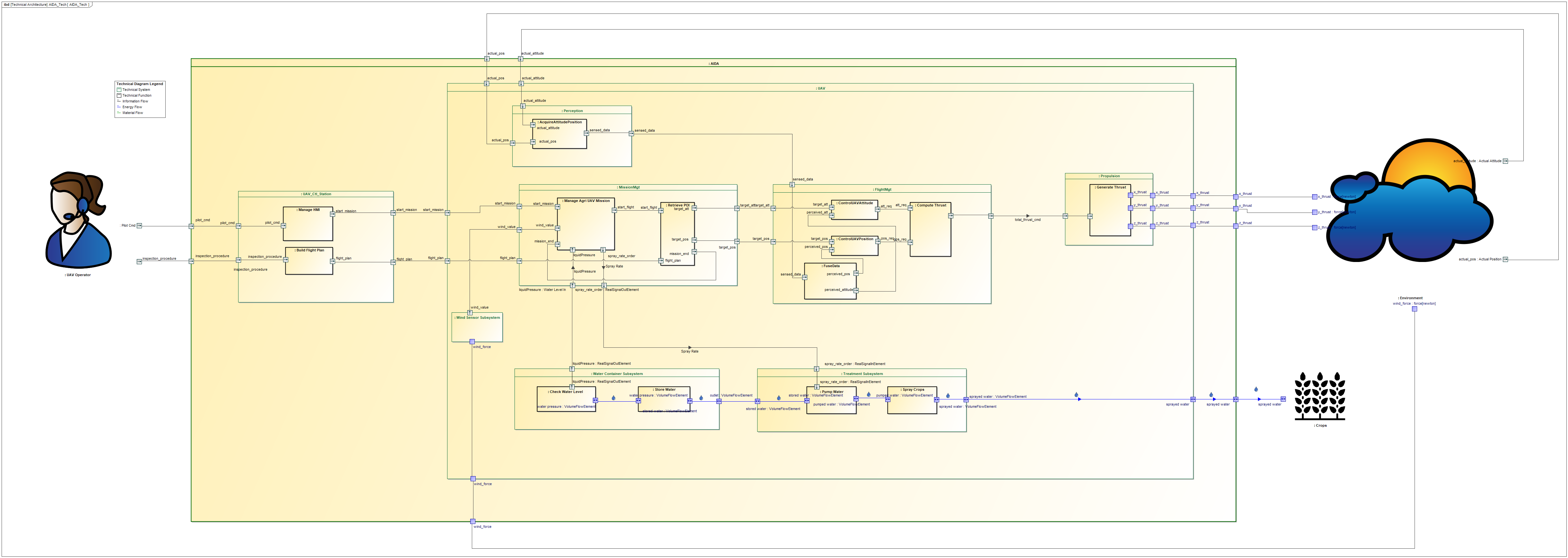
Agri UAV Logical Architecture
Modelica Language Overview
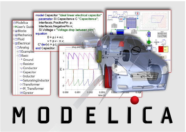
Image from https://www.modelica.org/modelicalanguage
Modelica is an object-oriented and equation-based language dedicated to the modeling and analysis of multi-physical systems. It is a defined by the Modelica Association. The Modelica language relies on both graphical and textual syntax. It makes it possible to combine Differential and Algebraic Equations (DAE) with discrete event systems. This language is well suited to represent flows of energy, signals, or materials, and any continuous interactions.
With Modelica, it is possible to create architectures made of sub-models connected by ports (undirected physical flows and directed signal flows). Models can be causal or acausal, and can represent hybrid systems (discrete and continuous). A good amount of free or commercial Modelica libraries are available for domains such as chemistry, automotive, neural network based AI, etc. The following figure shows examples of signal based components (integrator, PID, …) and physical based components (magnet, spring, tank, …) provided by Simulation X.
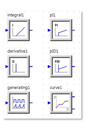
Signal library from Simulation X
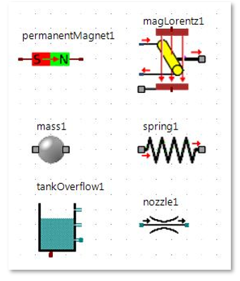
Physical components library from Simulation X
Application on the Agri UAV case study
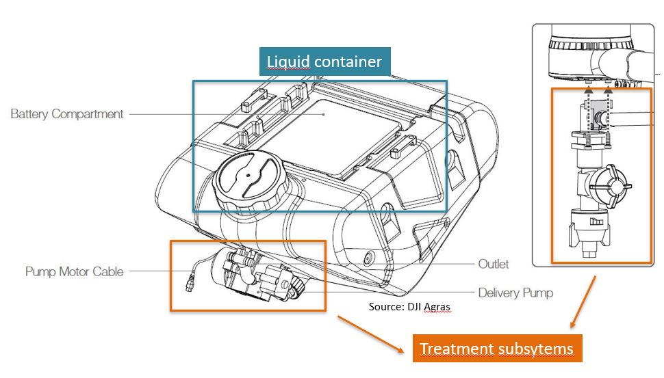
To illustrate the full approach, we use a simplified model of an Unmanned Aerial Vehicle (UAV) for agricultural domain. We use the following languages and tools:
- SysML in CAMEO Systems Modeler 19.0 SP4
- Modelica in Simulation X
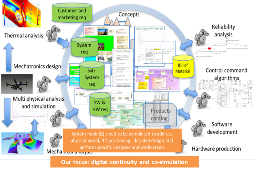
The goal is to provide a physical solution for the “Water Container Subsystem” and for the “Treatment Subsystem”. The following figures show the Modelica elements that will be used to design the physical solution of each subsystem.
Systems Requirements and SysML logical architecture
First we start with the following logical architecture made by a systems engineer.
Agri UAV Logical Architecture
In this article, we focus on the following requirements that shall be satisfied by the final architecture. Each of these requirements specifies the valid definition domain for the variables to be observed.
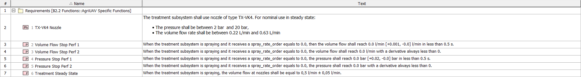
Systems requirements
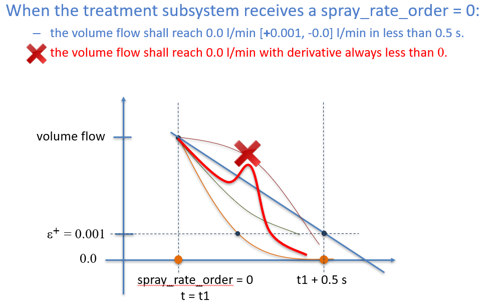
Note that in some of the requirements (req 3 and 5) we have introduced the notion of derivative. This requirement specifies that when the treatment subsystem is requested to stop, the flow shall continuously decrease. This is illustrated by the example of the following figure. All the curves are valid except the red one, which has a positive derivative at some point in time.
Initiate Logical Architecture in Modelica
The first step is to translate the functional/logical architectures defined in the SysML language toward an initial Modelica architecture in order to focus on the “Water Container Subsystem” and “Treatment Subsystem” with a language well adapted for the formalization and simulation of physical phenomena. This step results in a Modelica model containing Modelica partial models. The main advantage of using partial models to represent logical subsystems resides in their ability to be implemented using variants. Therefore, partial models can be seen as interface contracts that shall be respected by the engineers. Then, each individual model can be implemented with different architectures: this is what we will see next.
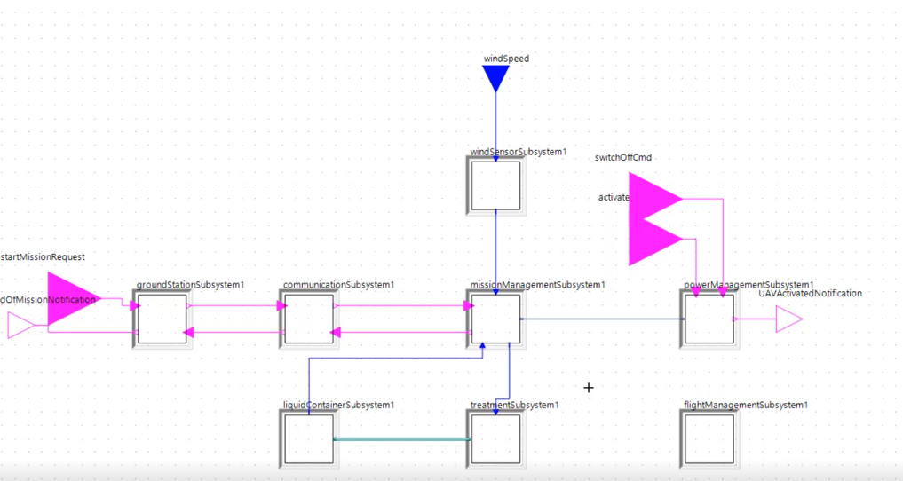
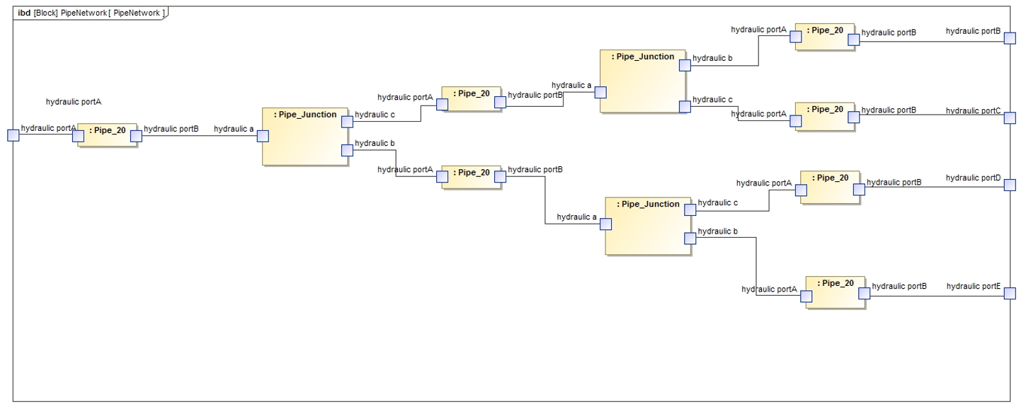
Modelica Initial Logical Architecture (Partial model)
In order to perform this translation, each Subsystem (SysML Block) is converted into a Modelica partial model. Each information flow is transformed into a Modelica Signal input or output and the hydraulic flow is converted into hydraulic ports and connectors in Modelica. We have used the SysPhS library (SysML Extension for Physical Interactions and Signal Flows Simulation) to type the ports. This library is available in Cameo Systems Modeler SP4 and has been specially built to specify physical and signal flows independently of the targeted simulation platform. Also, using this extension makes it possible to generate Simulink or Modelica models directly from the SysML model.
| Systems Engineering Concept | SysML Concept | Modelica Concept |
|---|---|---|
| Function | Block | Partial Model |
| Technical System Element | Block | Partial Model |
| Data Port | Proxy Port + Interface Block (SysPhS Signal Interface) | Partial Model |
| Trigger Port | Proxy Port + Interface Block (SysPhS Signal Interface) | Signal port |
| Enable/Disable Port | Proxy Port + Interface Block (SysPhS Signal Interface) | Signal port |
| Energy Port | Proxy Port + Interface Block (SysPhS Physical Interface) | Physical Port |
| Functional Flow | Connector | Connect equation |
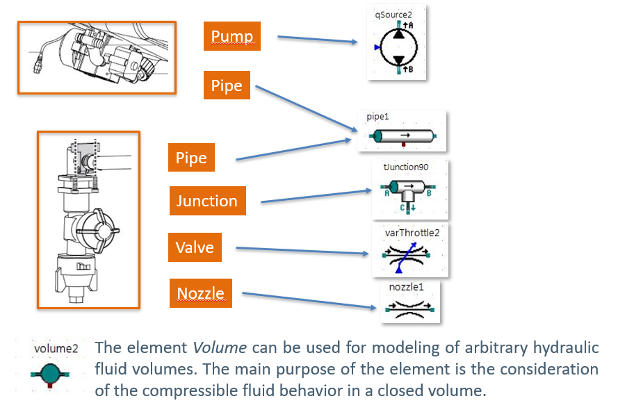
Define Physical components that fit with the logical architecture
To design the “Liquid container subsystem” and the “Treatment subsystem” we will use the following elements from a hydraulic library available in Simulation X.
First design of the logical subsystems
Using an available hydraulic library, we perform the following design for the “Water Container Subsystem” and the “Treatment Subsystem”. In addition, we build mock-ups for the other components in order to support simulation (this is not presented here).
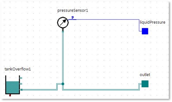
Water Container Subsystem Design
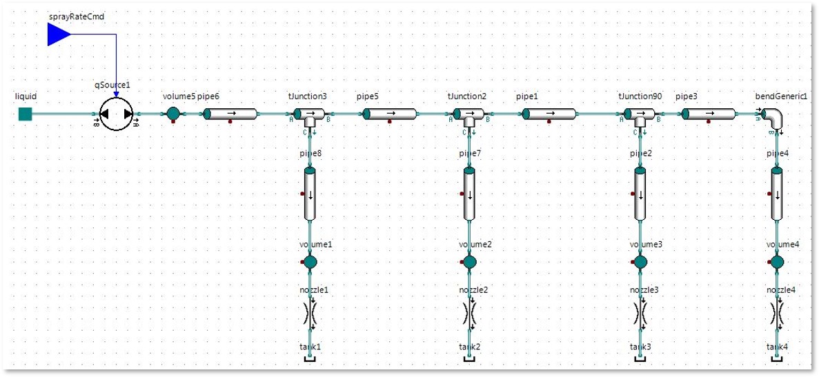
Treatment Subsystem Design
The simulation results of this first design allows us to see if the requirements are satisfied or not.
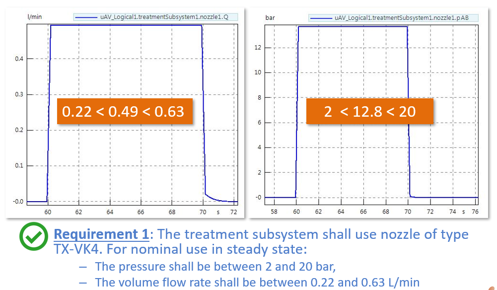
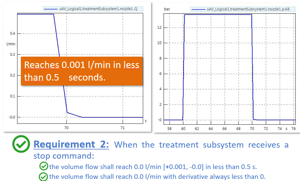
Volume flow (left curve) and Pressure (right curve)
At t = 70s, the stop command is received, then the volume flow (left side) and the pressure (right side) start decreasing. We see that the volume flow can not reach 0.001 l/min in less than 0.5s. Also, the pressure can not reach 0.02 bar in less than 0.5s.
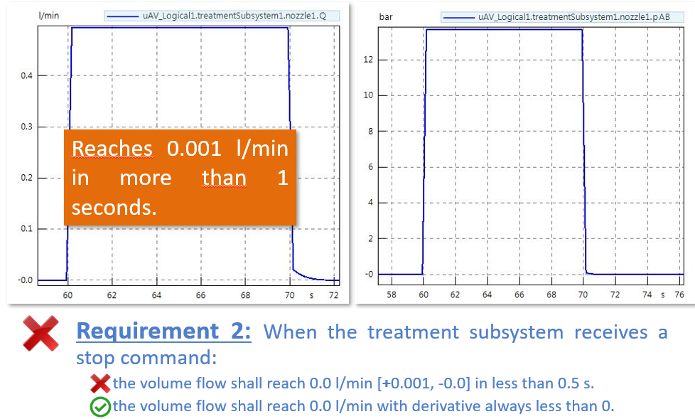
The requirement is not satisfied in the interval [70s; 72s].
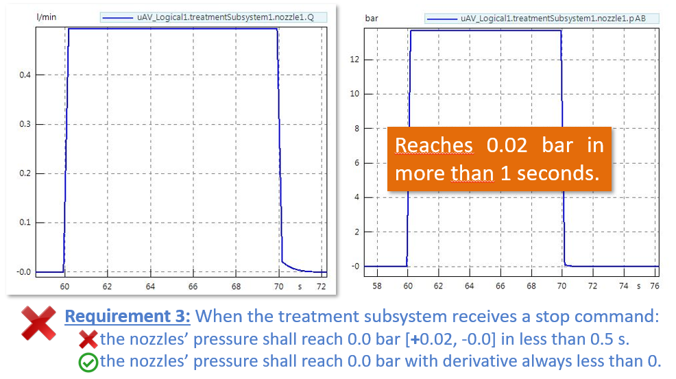
The requirement is not satisfied in the interval [70s; 72s].
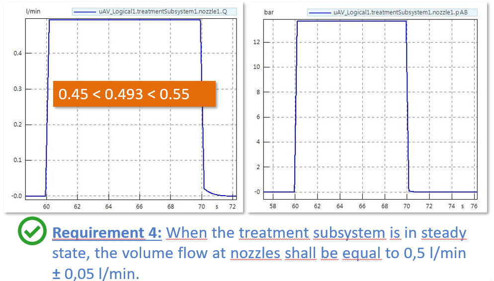
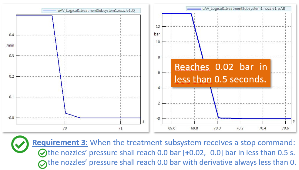
Volume flow (left curve) and Pressure (right curve)
From the simulation results, we can see that the first part of the requirement 2 (“Volume Flow Stop Perf 1”) and the requirement 3 (“Perform Stop Perf 1”) are not satisfied. Indeed, the spray does not stop in less that 0,5 s because of remaining pressure in the pipes. The solution can consist in adding valves before each nozzle that can be opened / closed on demand. The valve ensures that there is no remaining flow from the nozzles when it is not required. In addition, it ensures safety in case of failure of the controller or the pump. However it requires the creation of a new interface between the Mission Management subsystem and the Treatment subsystem. Therefore, this would trigger a request for change to the systems engineer to see the impact of creating a new interface between the mission management and the treatment subsystem.
Second design of the logical subsystems
A new interface is created as seen in the following image (valve_cmd).
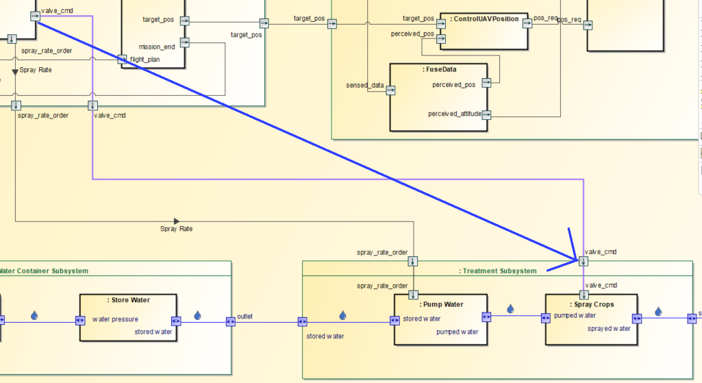
SysML Logical Architecture with new interfaces (valve_cmd)
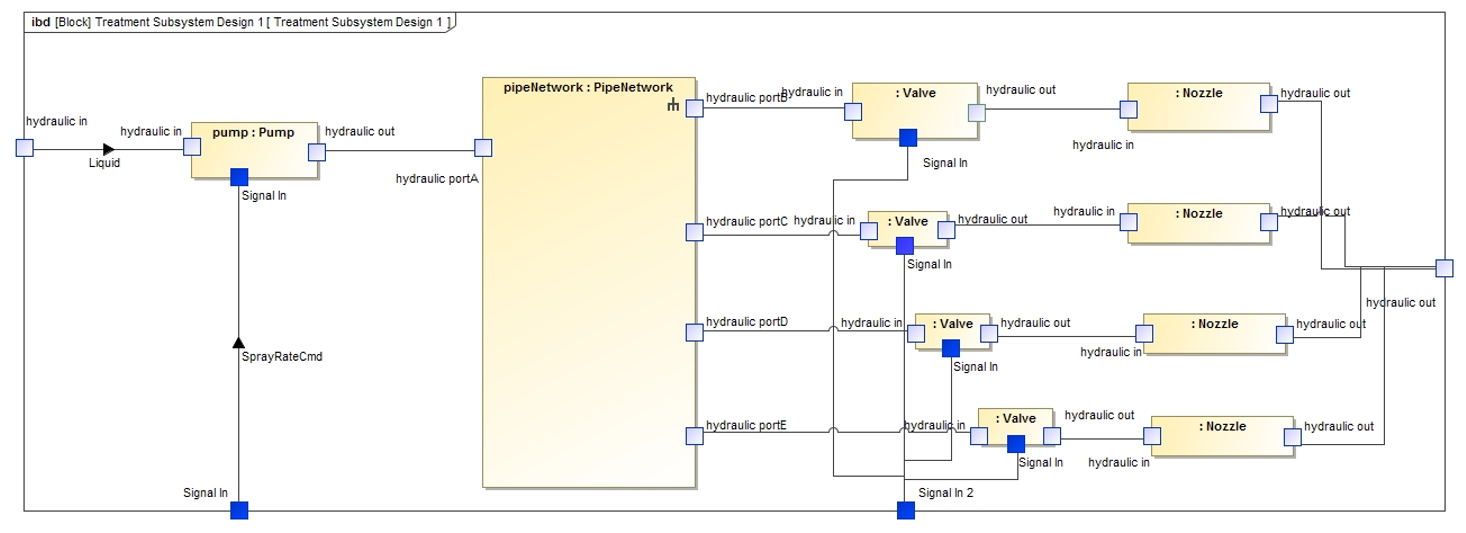
The design in Modelica results in the following Treatment Subsystem model:
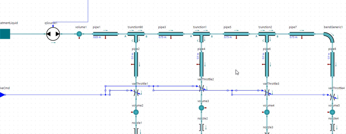
The following results show that the requirements 2 and 3 are now satisfied by the design.
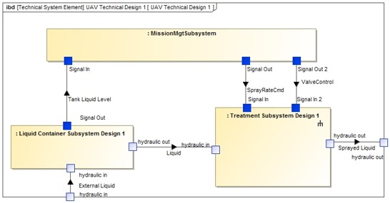
Feedback in SysML
The physical interfaces of the subsystems can be generated from the Modelica model. Here is an excerpt of the physical architecture that corresponds to a specific Modelica design. Note that we may find a lot of other types interfaces (electrical, mechanical, …). In that case, we suggest creating one IBD per physical viewpoint (physical domain). Now the treatment subsystem is « completely » specified (electrical and mechanical viewpoints are missing). We have identified a design solution that can satisfy the requirements. Hence, physical interfaces and sub-components can be built in SysML and traced to the rest of the model.
Synthesis
In this article we have proposed a coupling method between SysML (a Systems Engineering language) and Modelica (a physical modeling language). The proposed method includes a definition of system requirements and logical architecture using SysML and an initialisation of a partial Modelica model for physical architecting. Finally, when the virtual product can be verified against its requirements, this activity can lead to a change management loop with some updates to perform in the system definition (system requirements) with potential impacts on the SysML model.
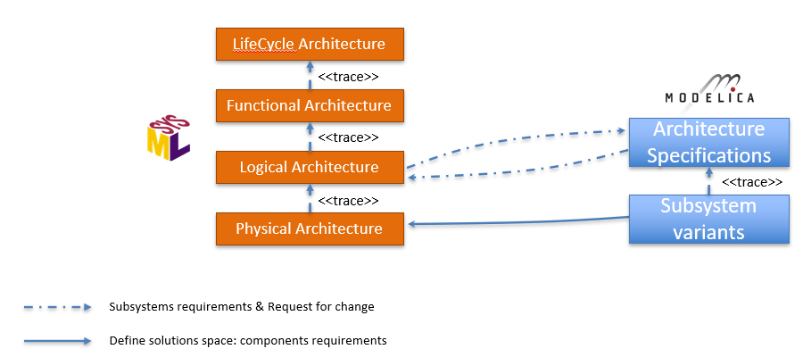
Design loop between SysML and Modelica
Going further
First, the initial model has been initiated manually from the SysML model. However, it would be possible to have a seamless code generation of Modelica partial models from the SysML models. Indeed, since partial models play the role of specification (interface contracts), it would be possible to adapt the approach to take into account the full process of configuration and change management.
Second, as Cameo Systems Modeler offers FMI co-simulation capabilities, it would be possible to generate and assemble FMUs from the Modelica models produced for some subsystems with FMUs generated from Simulink models (for the control subsystems). This would make it possible to characterize the co-simulation architecture from the logical architecture.
Enjoy MBSE !
Next articles to come…
- January 2021 – Co-simulation of SysML and other models through FMI