Part 9 – Co-Simulation of SysML and others models through FMI
This article is part of a monthly series entitled "Advanced MBSE with SysML and other languages".
In this article 9, we explain how to distribute some sub-systems of a logical architecture to a set of suppliers and to integrate and co-simulate their behavioural models in the SysML tool with the FMI standard.
This is the first article about using the FMI standard for co-simulation, but not the last! There is a lot to say about using FMI, and this article 9 can be considered as an introduction on using FMI in extended enterprise, through a fairly simple sample case. At the end of this article, we mention some challenges and advanced topics that we plan to work on during 2021, and this work will lead to other articles.
Context
In the previous articles (part 1 to part 8), we introduced a method based on the SysML notation to support the following systems engineering activities:
- Formalization of functional needs
- Refinement and definition of systems requirements
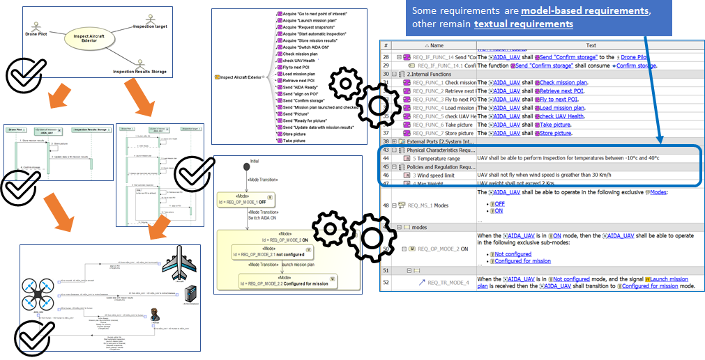
- Early validation of stakeholder’s needs using Functional Simulation
- Definition of Functional and Logical Architectures
- Optimization of Logical Architectures
- Digital Continuity between SysML and Simulink
- Digital Continuity between SysML and AADL
- Digital Continuity between SysML and Modelica
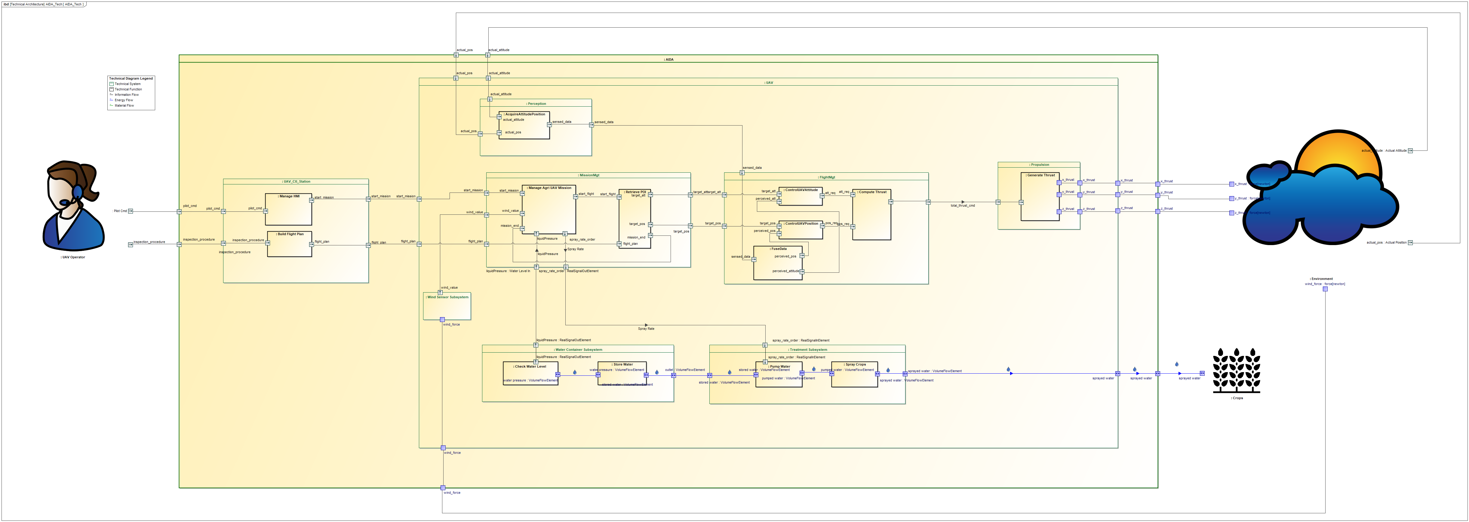
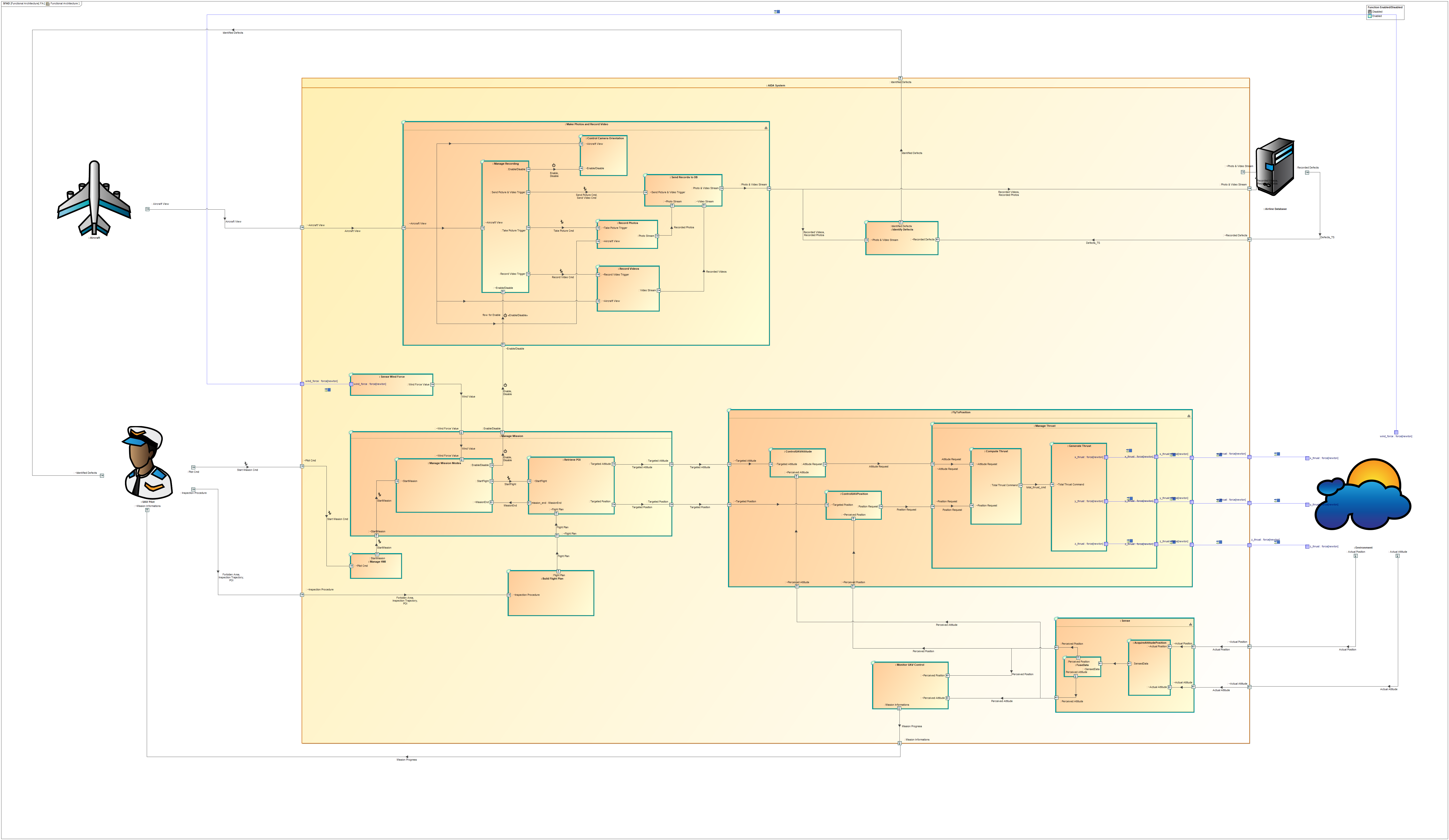
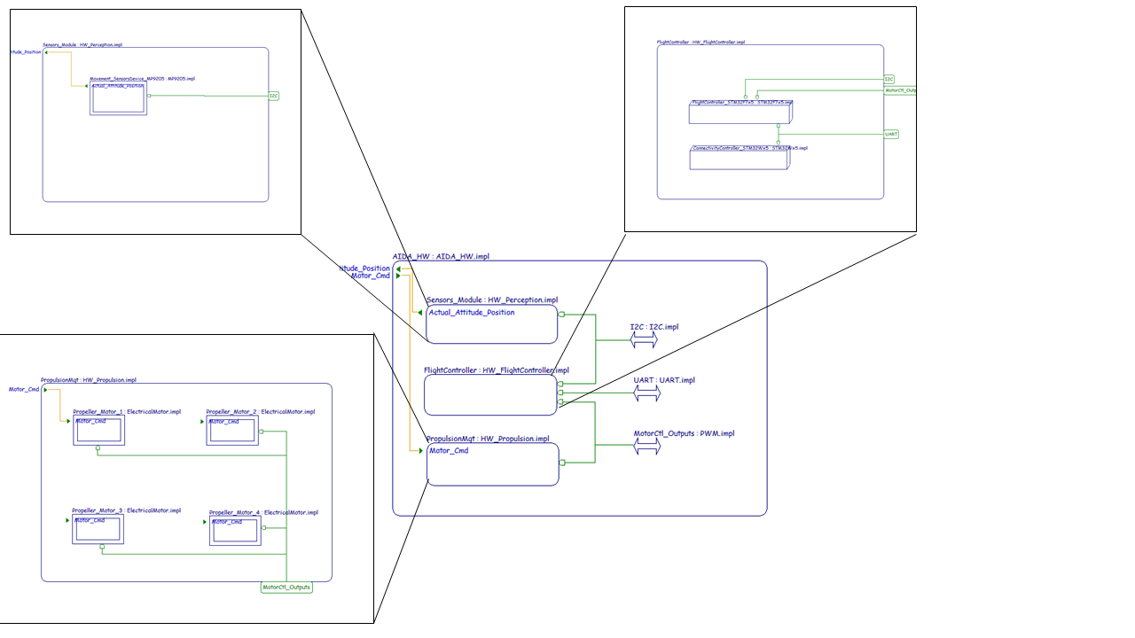
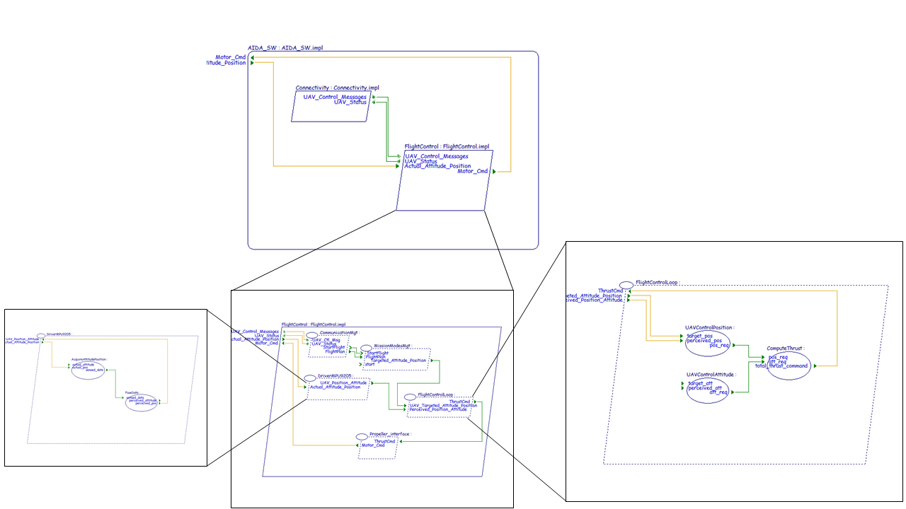
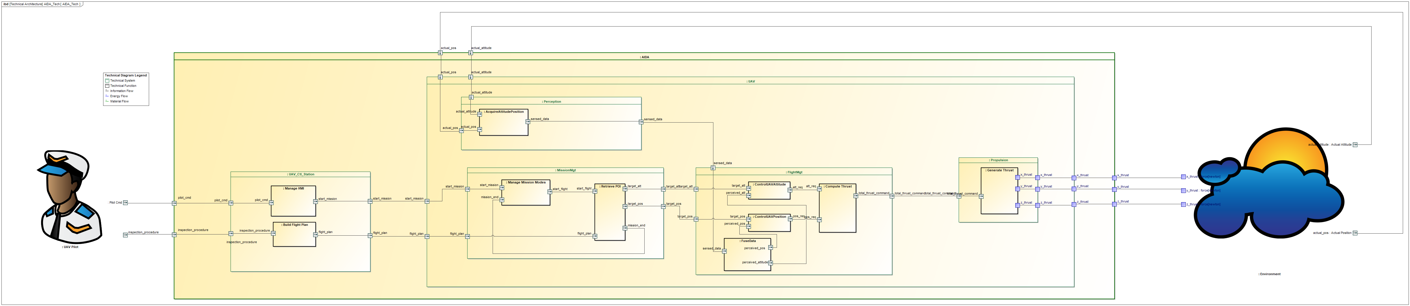
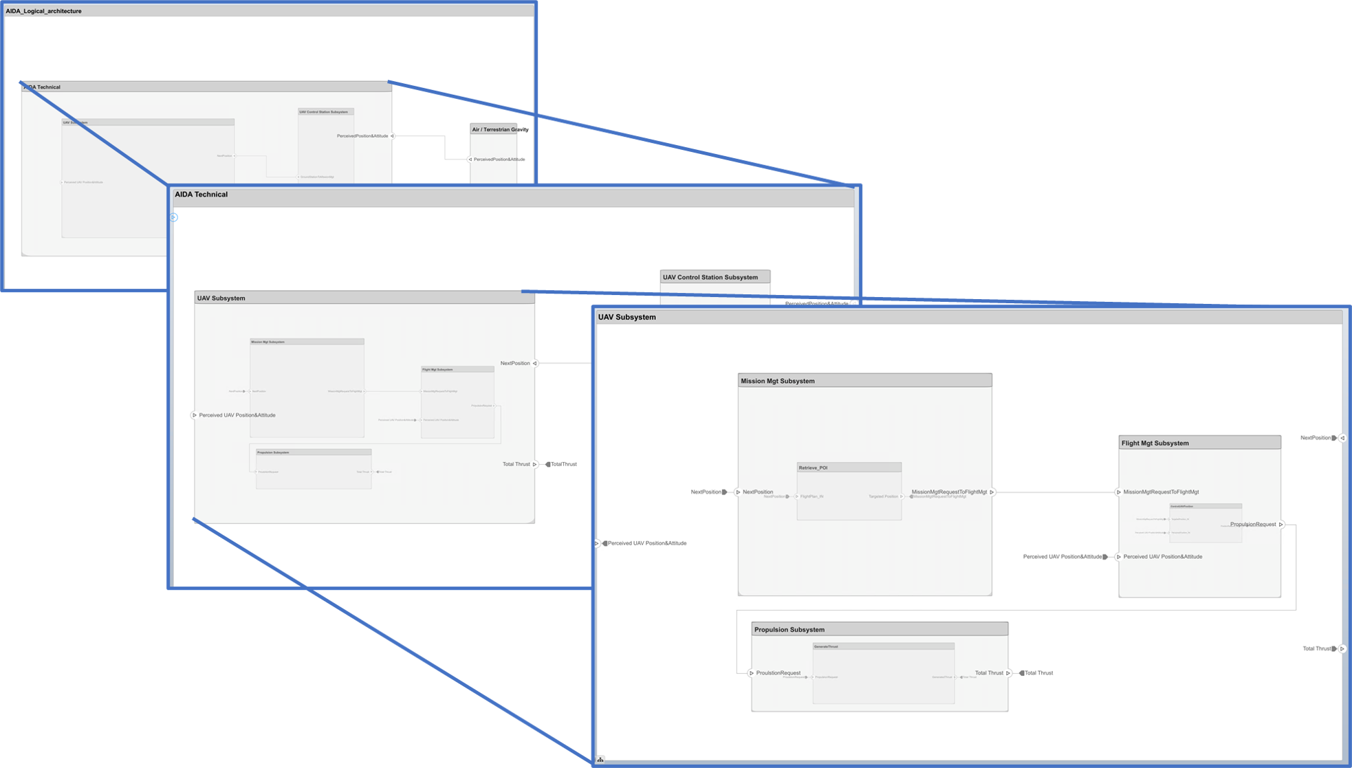
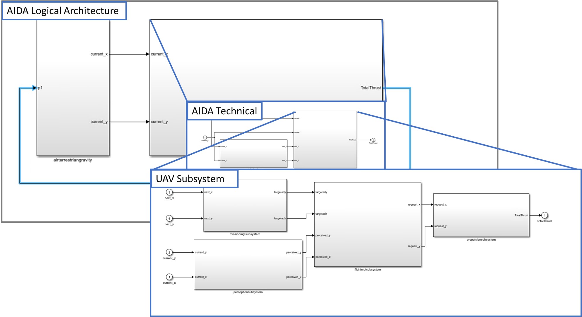
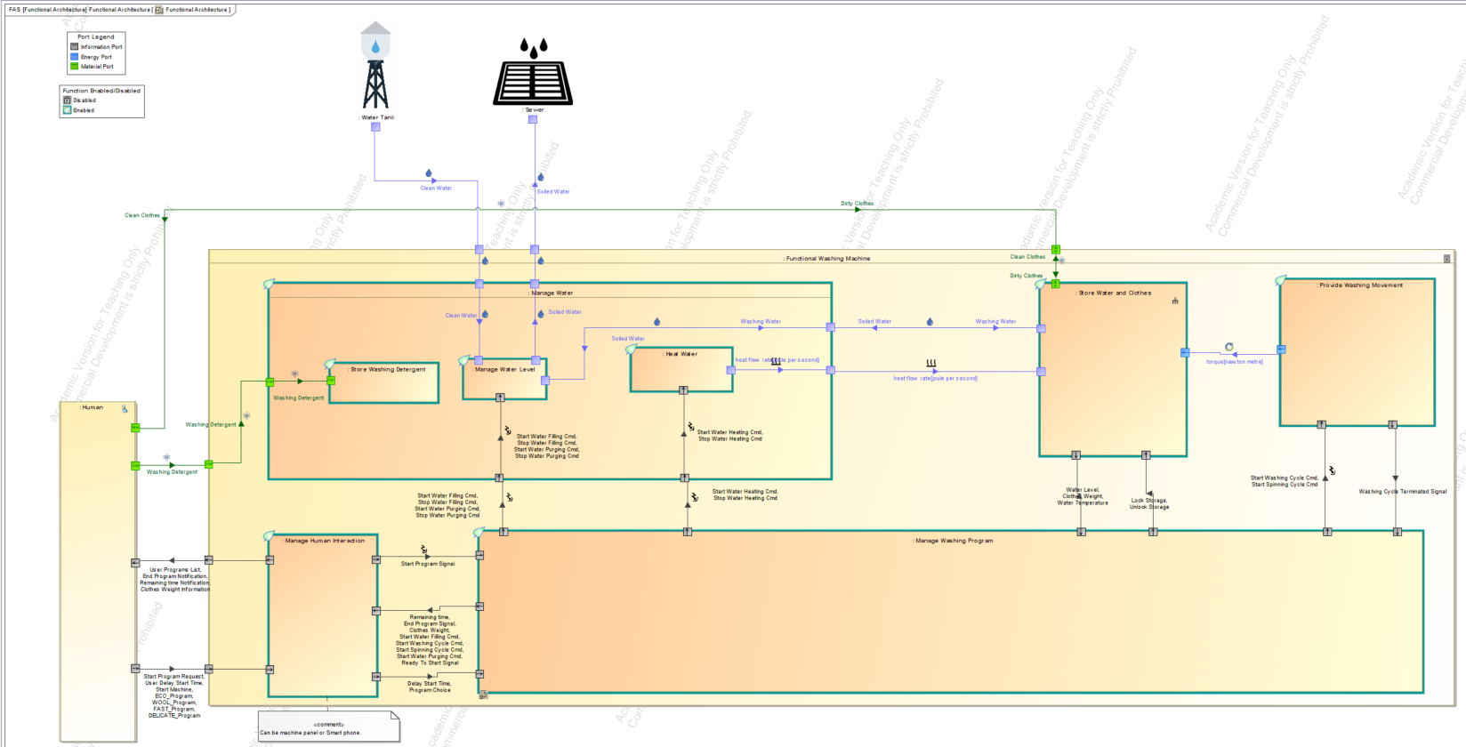
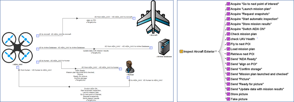
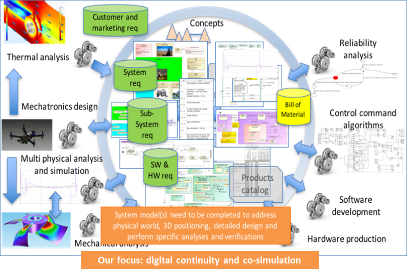
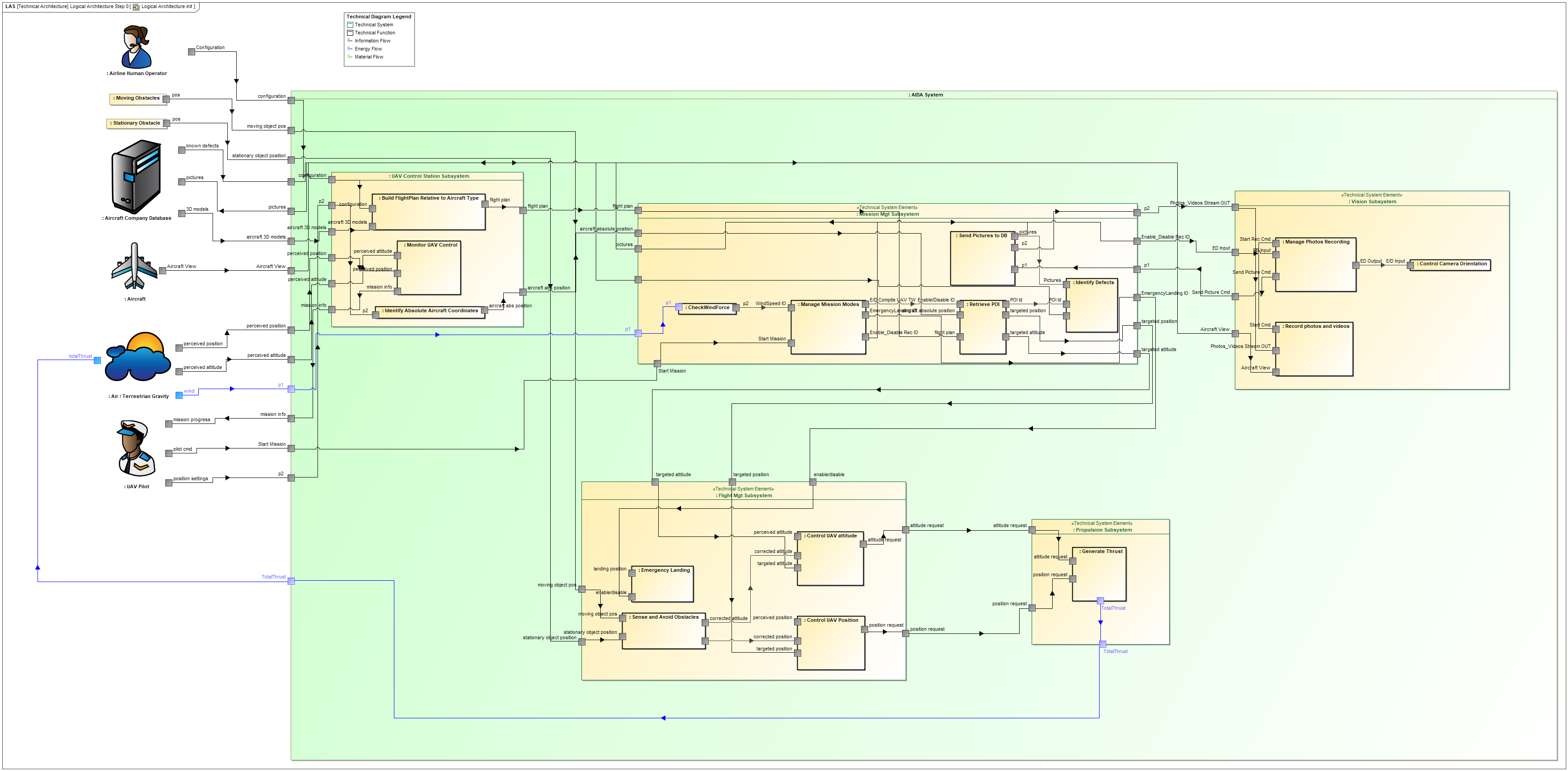
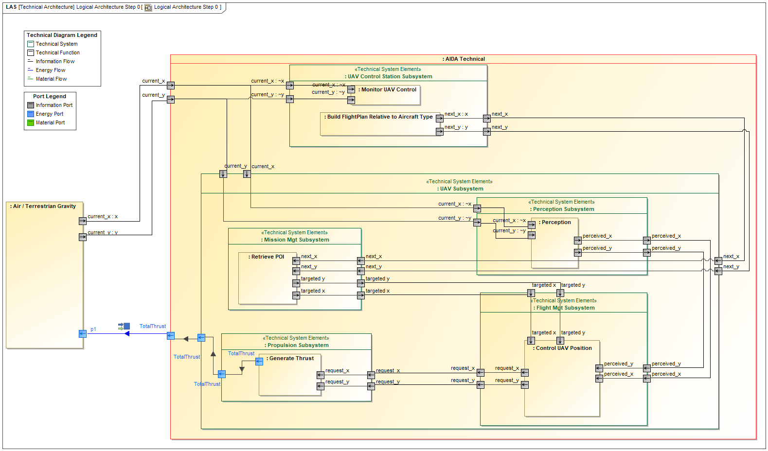
This article starts with the availability of an Aircraft Inspection By Drone Assistant (AIDA model inspired from the IRT St Exupery case study) logical architecture. It is illustrated below:
The different subsystems (logical components) will be assigned to different suppliers. We expect each supplier to develop a behavioural model of the assigned subsystem before developing the real subsystem. The idea is to integrate all the behavioural models provided by the different suppliers into a central repository, and to co-simulate all those models (simulate all those models concurrently) to evaluate the global behaviour and validate that it behaves as expected. We will use the FMI standard for co-simulation. This is explained in the next paragraphs, before we show the practical steps for integration and co-simulation of the behavioural models through FMI.
Functional Mock-Up Interface (FMI) Standard Overview
The Functional Mock-Up Interface (FMI) is a standardized interface to exchange dynamic models issued from various simulation tools and package the model as a combination of an XML model description file, executable binary files and eventually C code files into a single zipped file.
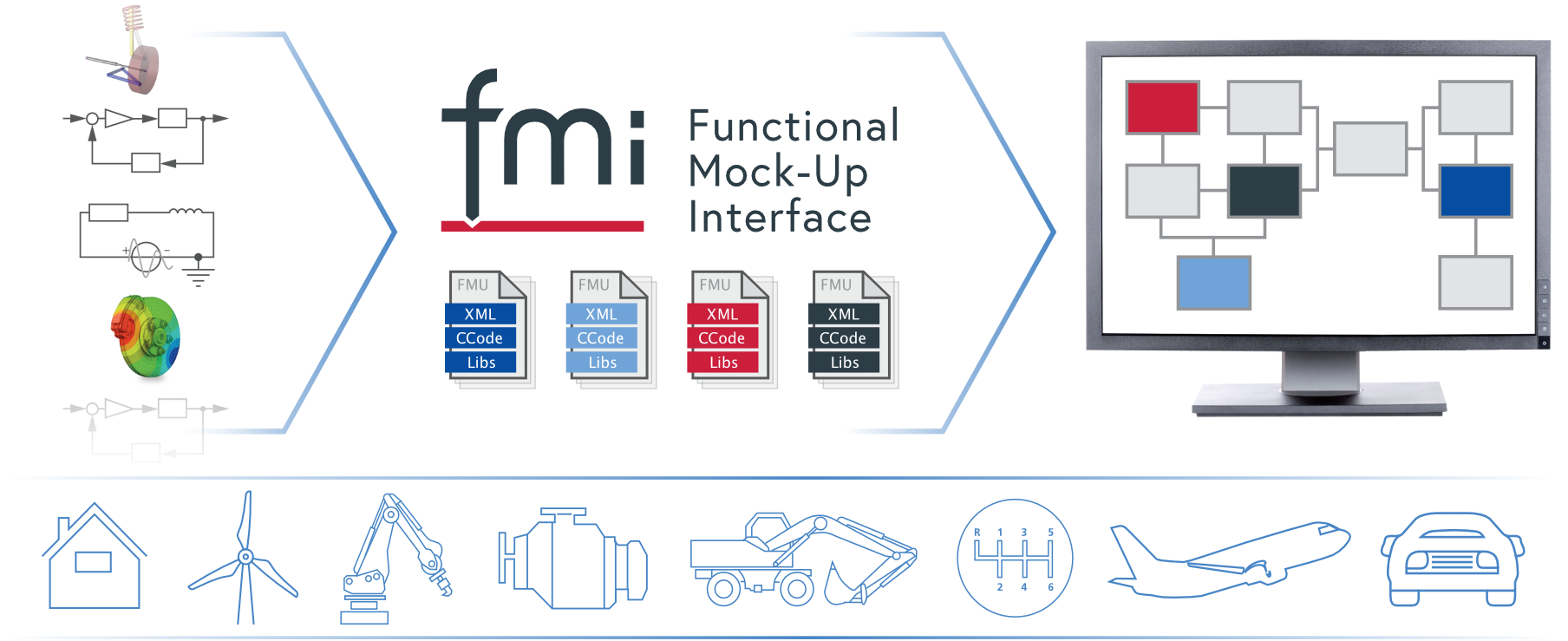
https://fmi-standard.org/
This makes it possible to extract models from several different simulation tools, and integrate heterogeneous models into a single simulation tool and provide the model as a “black-box” for preservation of intellectual property when it is required.
Introduction
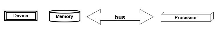
- All components that need to support FMI shall comply with a standard interface that brings services to perform a time step in a model: set input data, progress in the behaviour from one time step – fmiDoStep (or fmi3doStep in the most recent version 3), and get results (output data)
- Basically, an FMI-compliant component is packaged into a Functional Mockup Unit (FMU), which is a zipped file (*.fmu) containing:
- modelDescription.xml
- Implementation in source and/or binary files that complies with FMI services
- Additional resources if necessary
In the next paragraph we present the model description file and the principles of FMI for both model exchange and co-simulation, with a particular focus on co-simulation.
Model Description file structure
The modelDescription file structure is presented below:
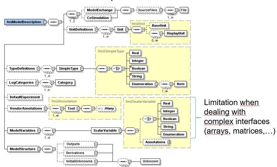
Model description structure (from FMI specification)
Principles of model sharing with FMI
- FMI for Model Exchange:
This approach is proposed to extract model data from a simulation tool without its solver. It is then possible to re-integrate the extracted model in another tool where an appropriate solver is available.
Note: As our article will focus on FMI for Co-Simulation, we do not go into detail on the Model-Exchange principles in this article. If you are interested in more details about Model Exchange, please refer to the FMI Standard.
- FMI for Co-Simulation
This approach makes it possible to extract an executable simulation model from a specific tool. The executable is then used as a component library to be integrated in a wider environment. This mode is particularly useful to integrate several models coming from different suppliers to evaluate the overall consistency of the complete system.
FMI for Co-Simulation
- FMI for Co-Simulation Export:
- C code and xml file generation with embedded solver
- Archives (.zip) sources and binaries into a .fmu file
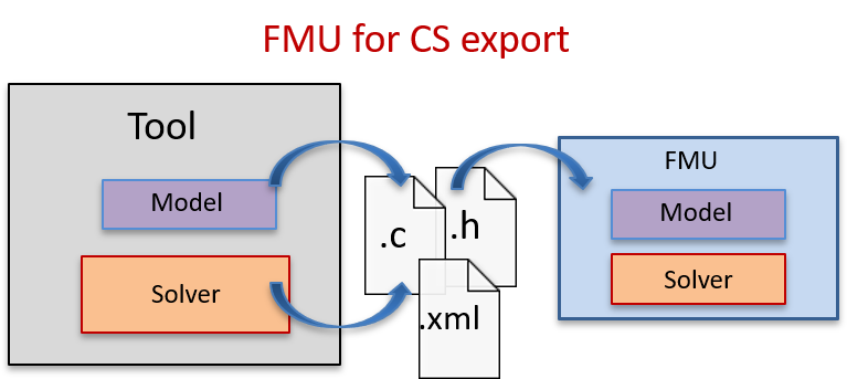
FMU for Co-Simulation Export
- FMI for Co-Simulation Import:
- Requires a Master-Algorithm (MA) which synchronizes fmu exchanges
- FMUs can be connected to the other parts of the model
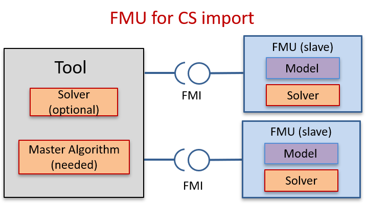
FMU for Co-Simulation Import
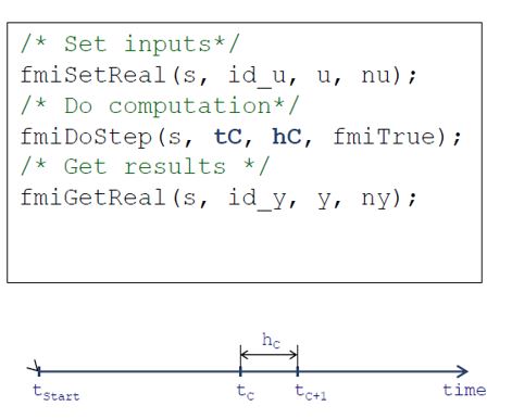
The Master Algorithm executes individual FMUs at regular communication time steps (hC) and propagates the model outputs to their connected models. This mechanism is called by standardized FMI APIs as illustrated below:
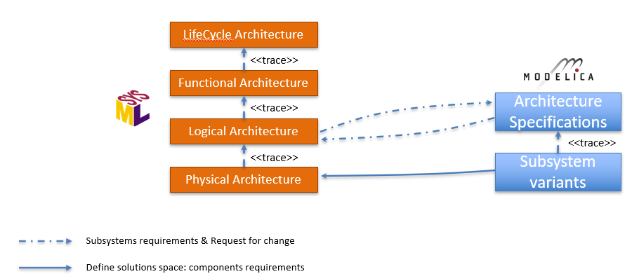
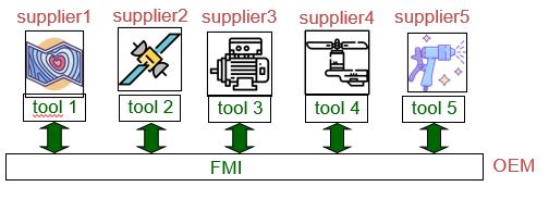
Systems Design and Supply chain process
As explained in the introduction of the article, we want to perform early Verification and Validation of system requirements and verify the global behaviour that is split between the different subsystems. We distribute the subsystems definition models to different suppliers (specialists of different domains) and request them to provide a detailed behavioural model that is compliant with the FMI standard.
This process is illustrated in the figure below:
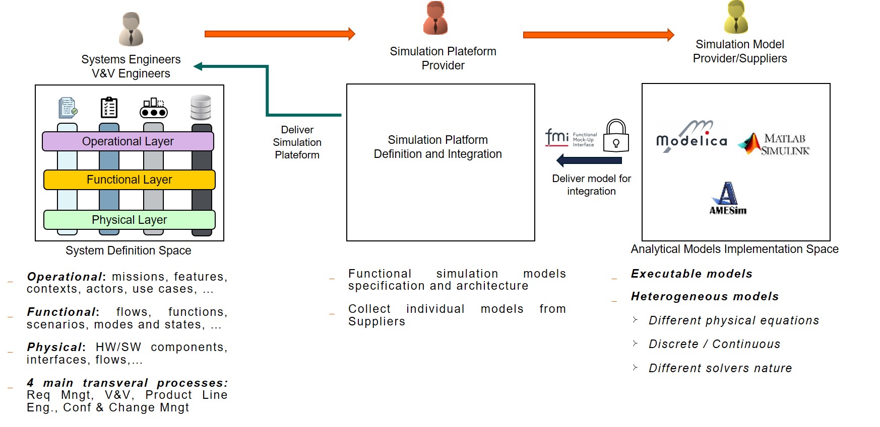
We collect the different models provided as executable files (“black-box”) to preserve the supplier Intellectual Property (IP). From the integrator side, we can now integrate those potentially heterogeneous models (i.e.: developed with different simulation tools and solvers) into a single tool and verify the overall execution of the different models and their interoperability. This is possible thanks to the FMI standard that ensures this interoperability.
Note: This article briefly presents the co-simulation of different logical components developed in a well-defined sequence from mature specifications. In industrial reality, it may happen that the subsystem behavioural models are developed concurrently with the system architecture definition. We do not give details about the full industrial process of exchange with suppliers and gap analysis for alignment with definition models when both definition and detailed behaviour have been defined concurrently. If you want to know more about this industrial process, you can look at our CSDM 2020 conference joint article with Renault: “Applying Model Identity Card for ADAS V&V“.
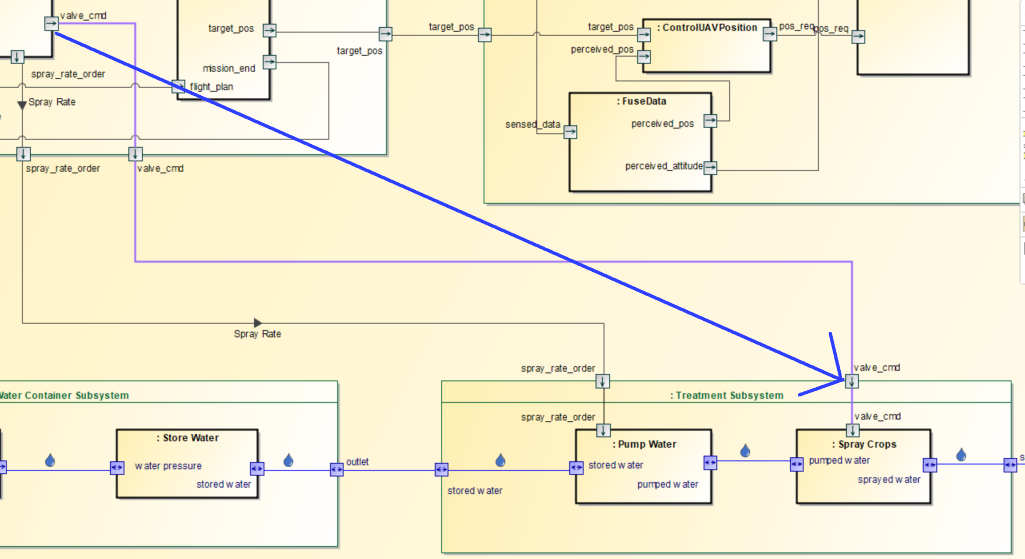
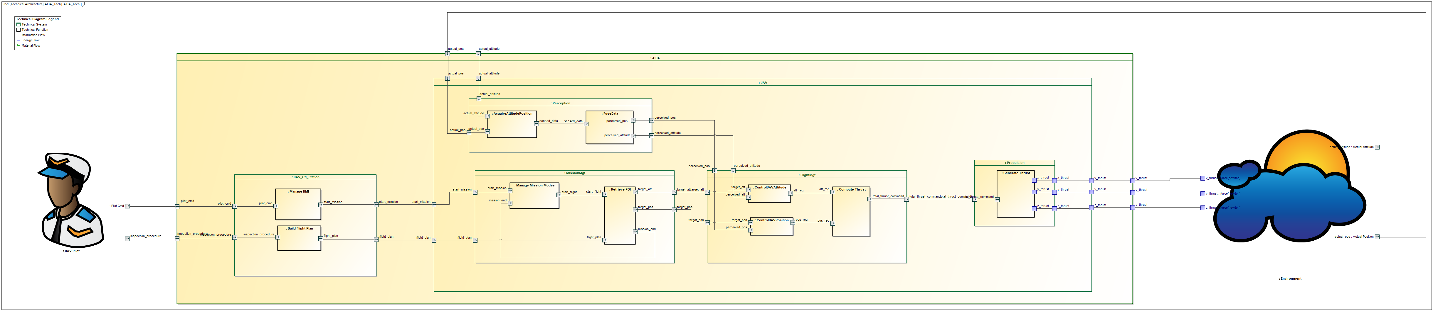
Illustration on AIDA case study
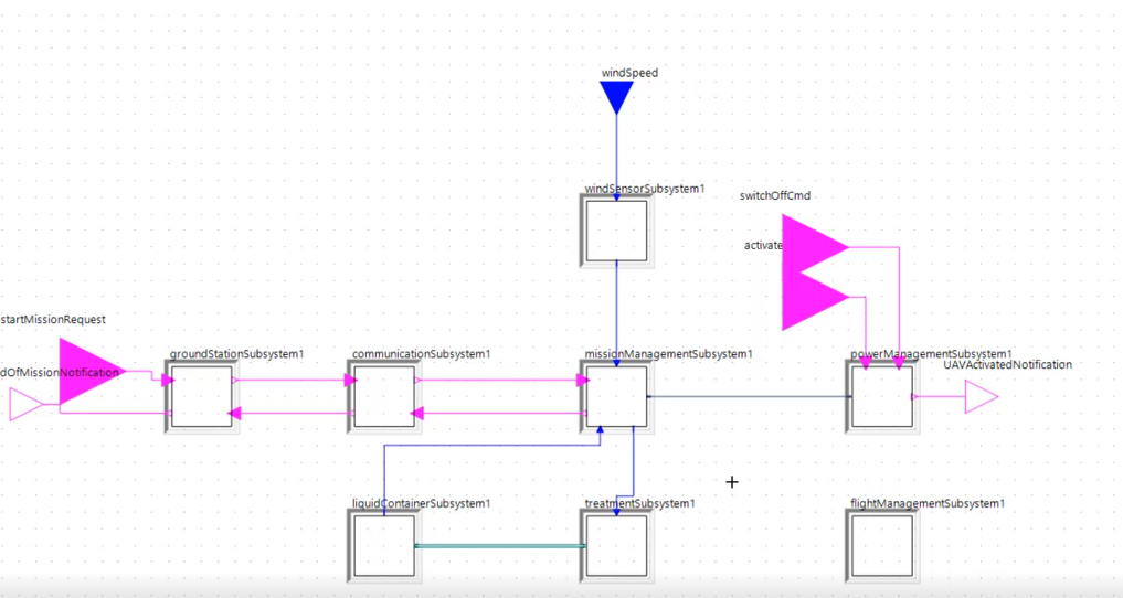
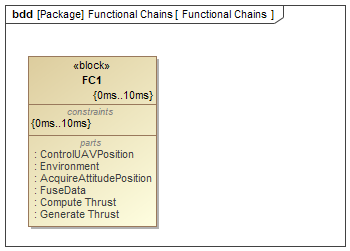
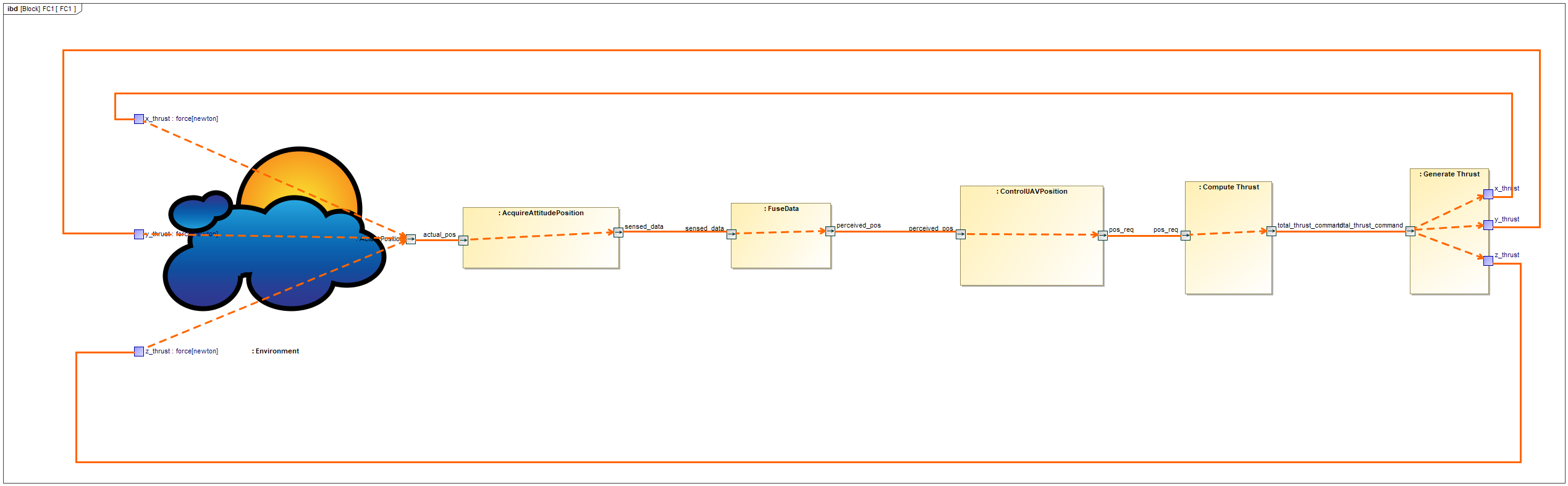
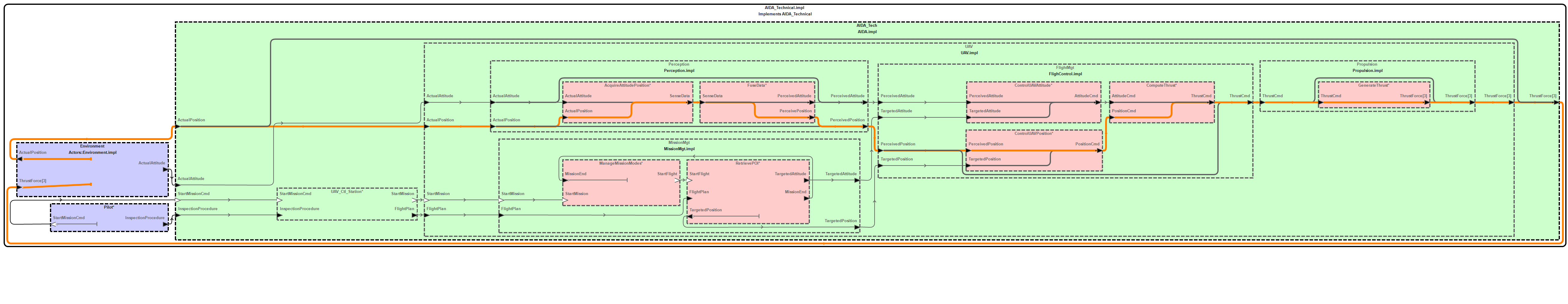
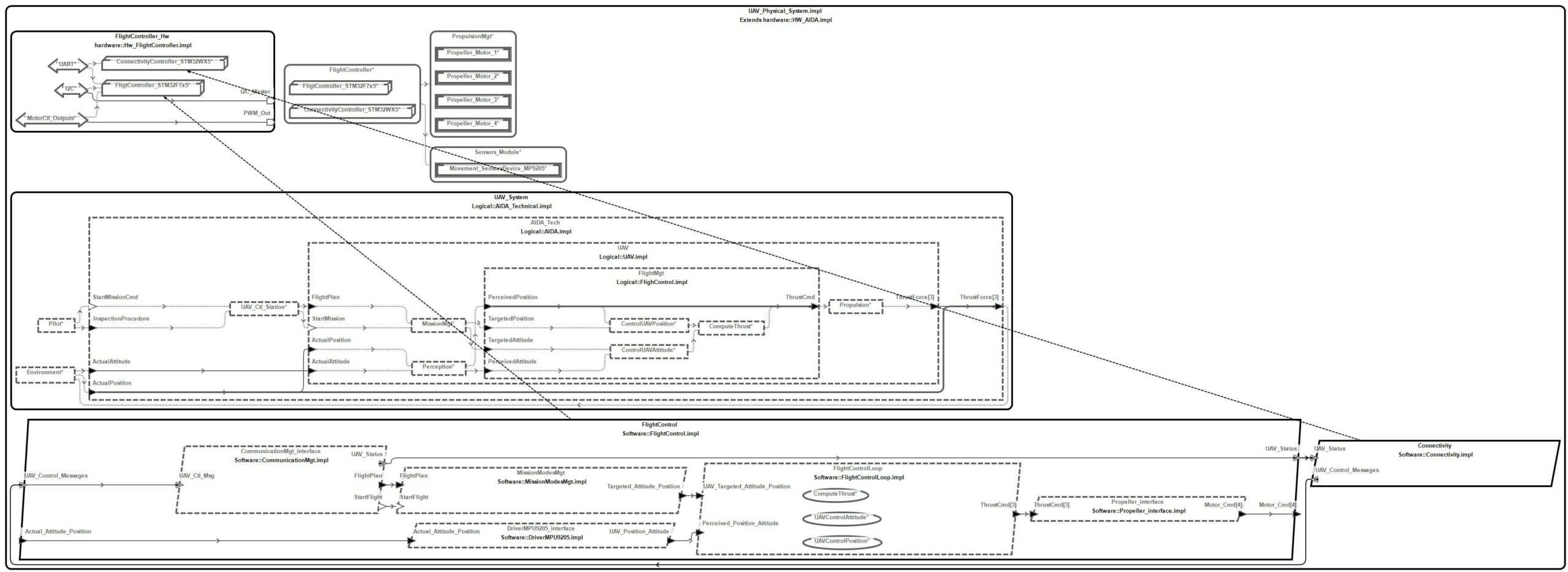
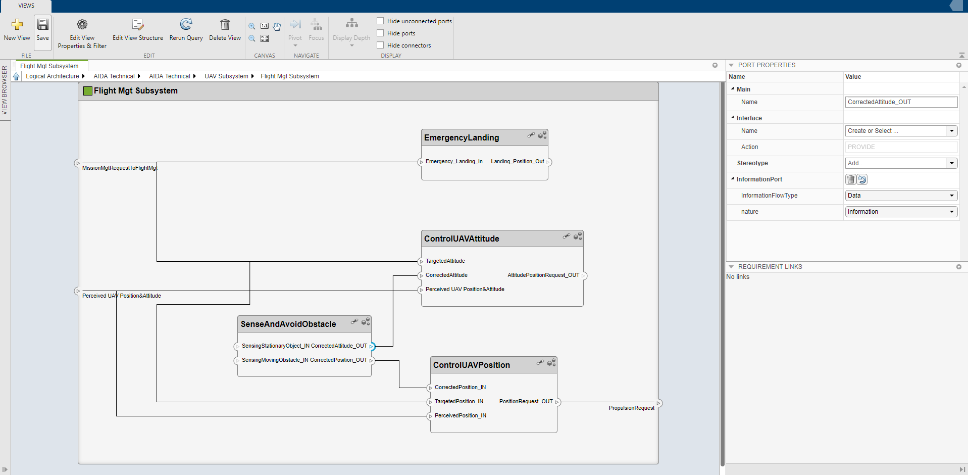
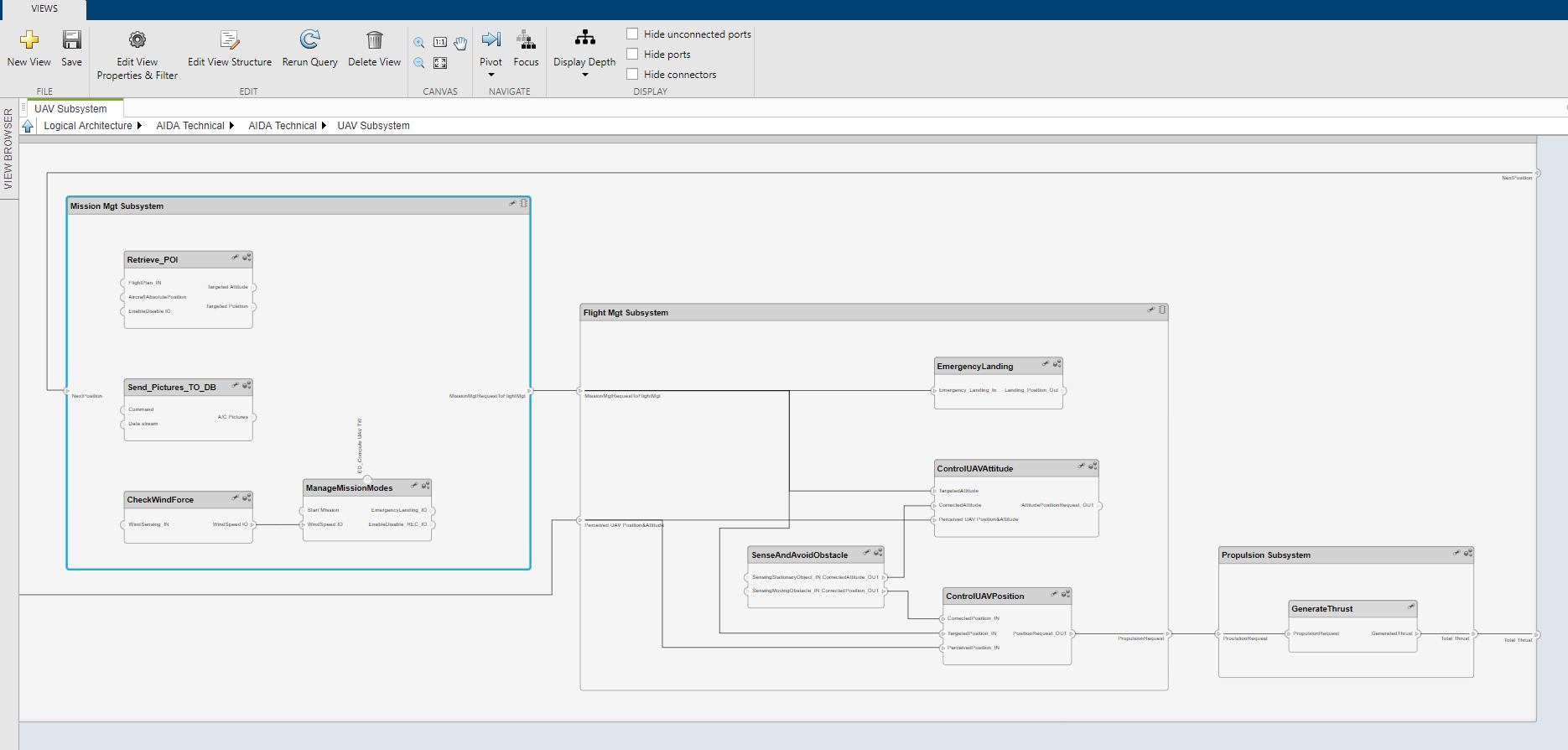
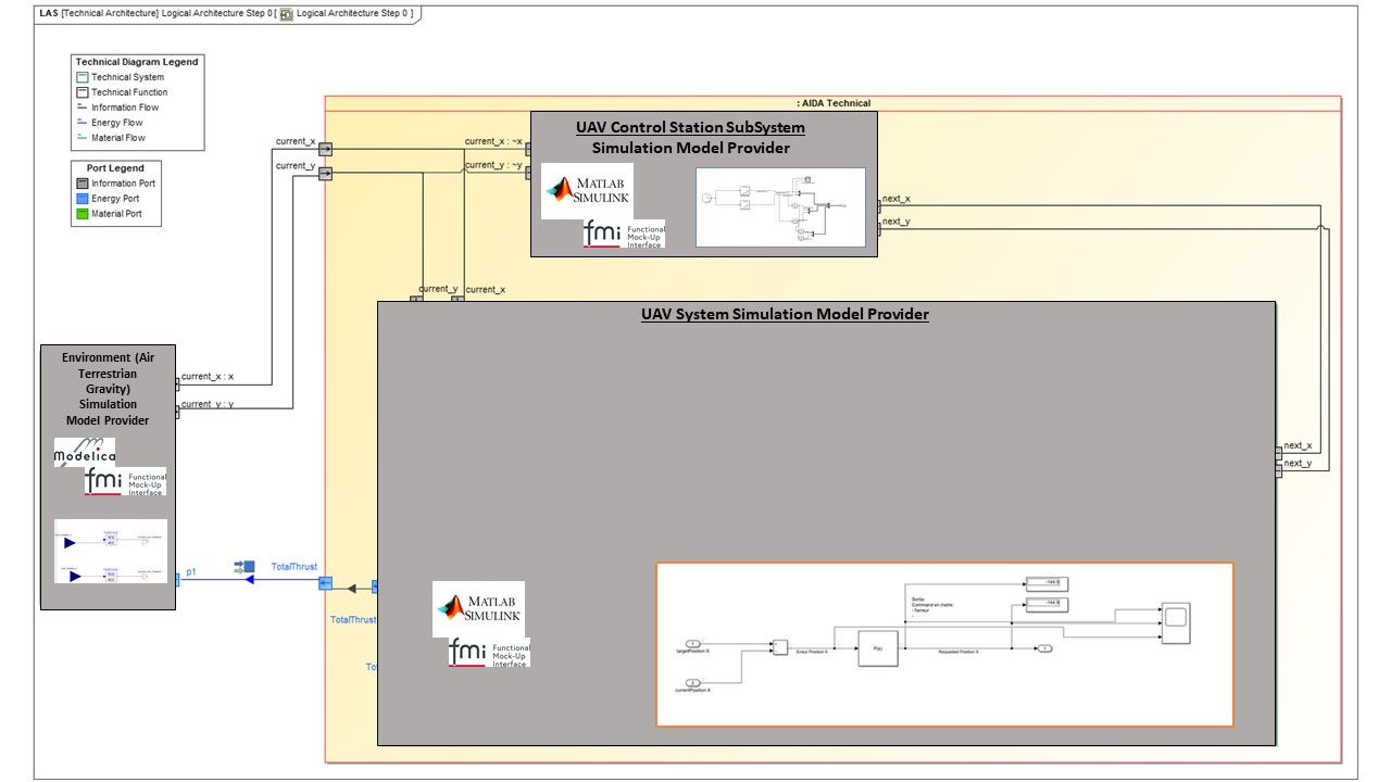
In our example we use the AIDA Unmanned Aircraft Vehicle System. The logical architecture of the UAV System is shown in the figure below:
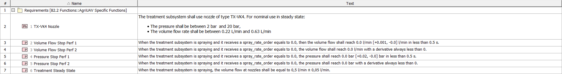
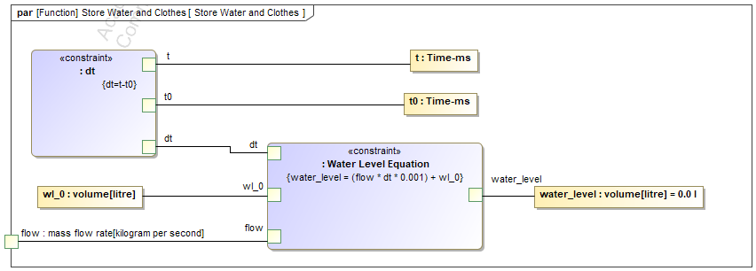
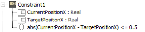
It is possible to define verification criteria based on requirements formalized by SysML constraints, as illustrated below for controller accuracy (0.5m):
Now we provide specifications to our suppliers (including a SysML model of the context of each subsystem and requirements on the expected behaviour). Suppliers will have to develop the behavioural models.
Note: we illustrate the full process for only two subsystems (UAV Control station and UAV system) and one external system (Air gravity) to limit the size of this article. But what is shown can be applied in the same way to many other subsystems and external systems.
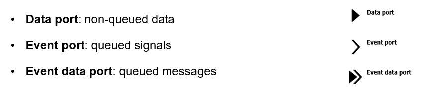
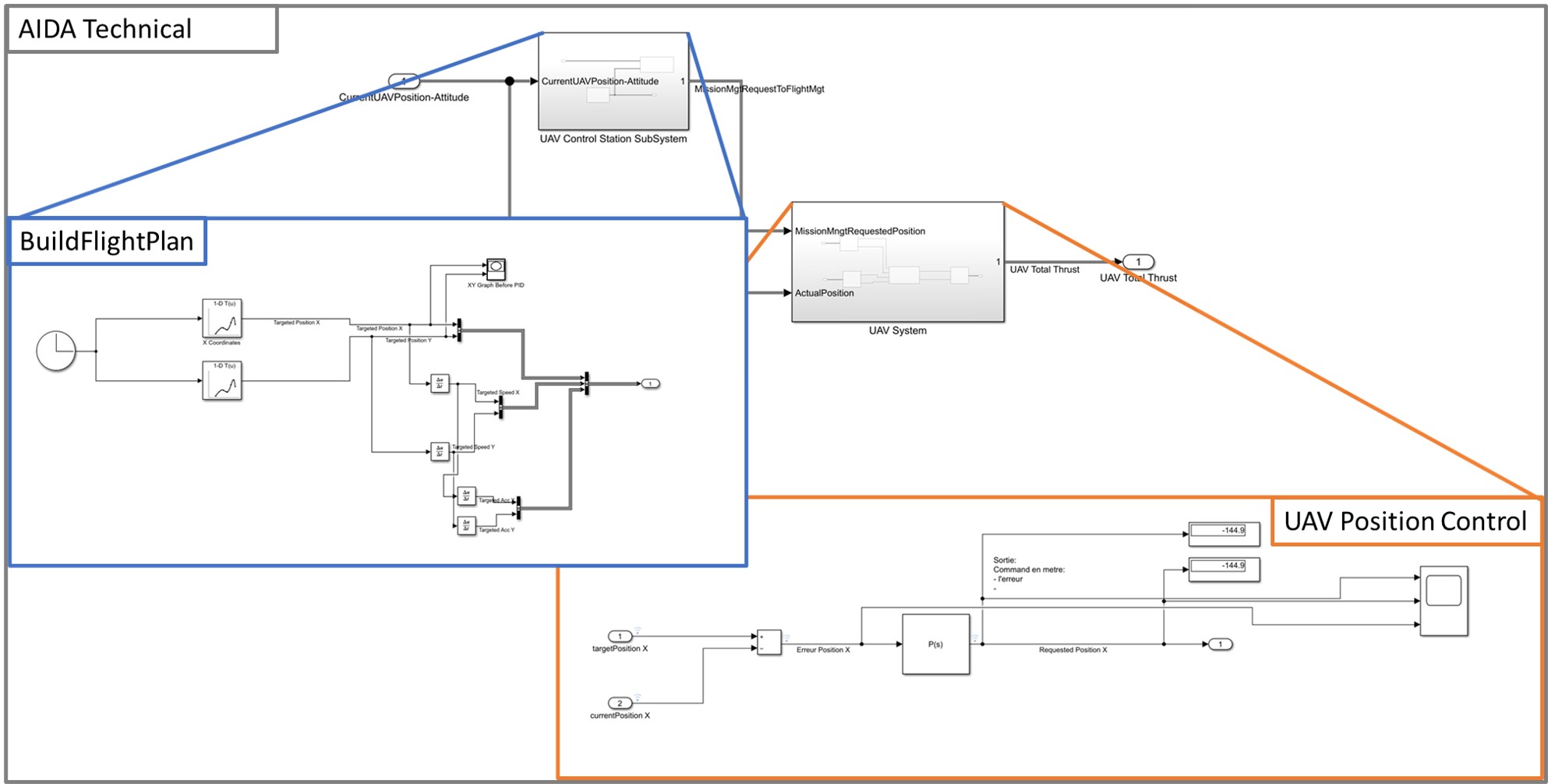
- AV Control Station – Behavioural Model Provider:
This actor is in charge of developing and to providing the behavioural model of the UAV Control Station with a dedicated focus on the Build Flight Plan function behaviour. In this example, the UAV Control Station Model provider uses the MATLAB / Simulink 2019b tool and wants to provide the UAV Control Station behavioural model as a “black-box” executable model to the System Integrator using the FMI for Co-Simulation 2.0 export capability integrated in MATLAB / Simulink.
- UAV System (vehicle) – Behavioural Model Provider:
This actor is in charge of developing and to providing the behavioural model of the UAV System and in particular of the UAV Control Position and attitude functions behaviour. This behavioural model is developed using the MATLAB / Simulink 2019b tool and is provided as a “black-box” executable model to the System Integrator using the FMI for Co-Simulation 2.0 export capability integrated in MATLAB / Simulink.
- Environment – Air Terrestrial Gravity – Behavioural Model Provider:
This actor is in charge of developing and to providing the behavioural model of the UAV Environment, especially of the Air / Terrestrial Gravity. This model is required to model the effects of the external environment on the UAV System. We suppose that OpenModelica v1.16.2 is used to develop these models and to export the behavioural model using the FMI for Co-Simulation 2.0 export capability integrated in OpenModelica.
This responsibility sharing is summarised in the figure below:
Generation of Functional Mock-Up Unit from MATLAB/Simulink
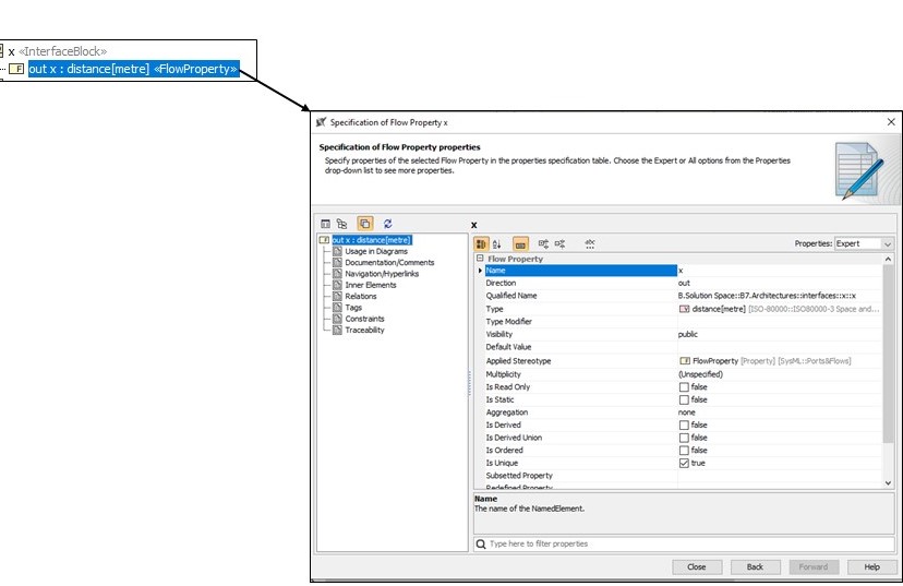
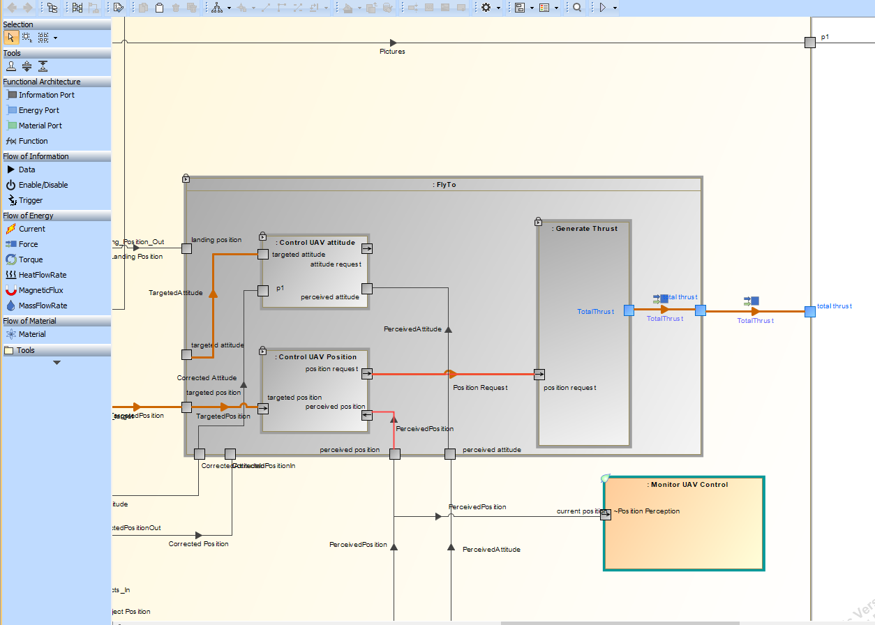
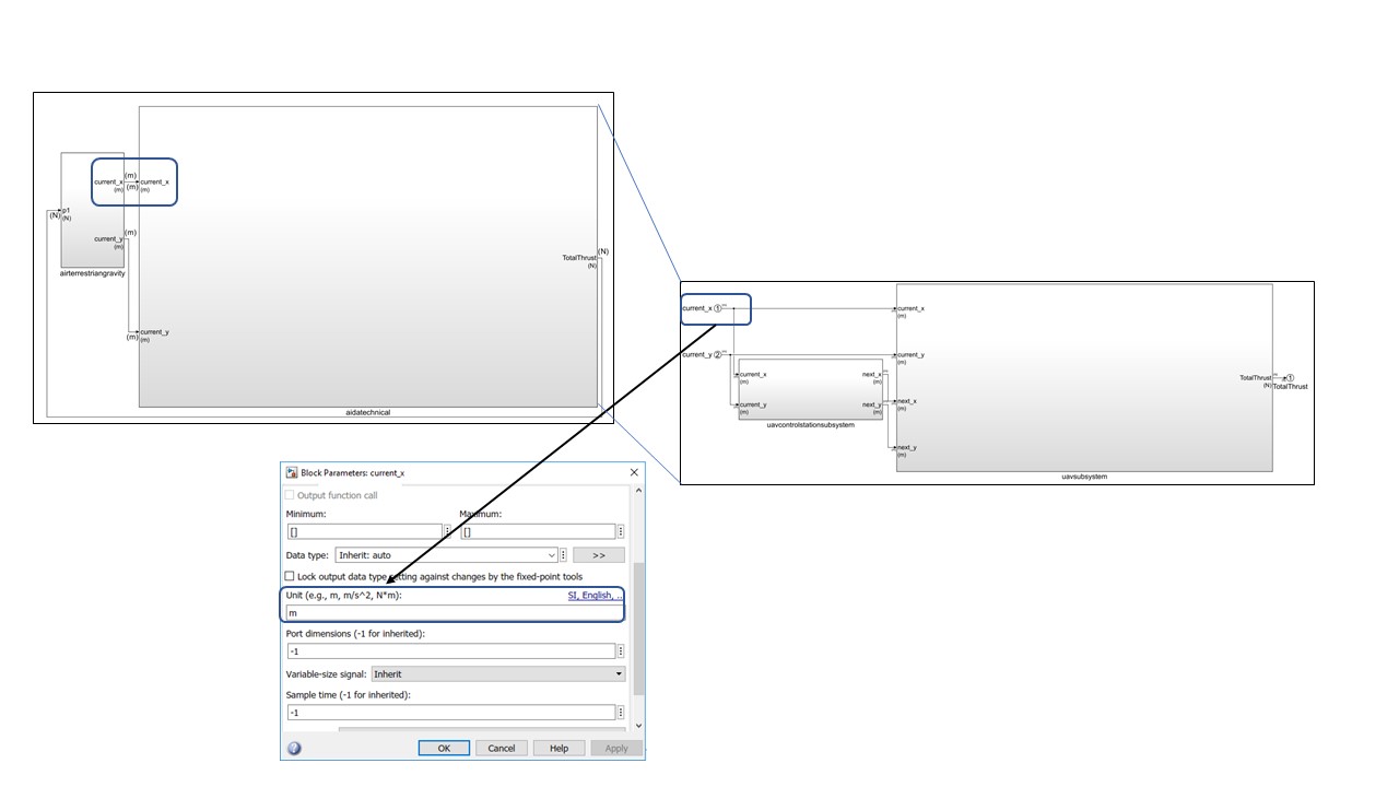
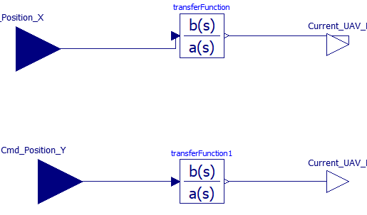
Each supplier shall develop its behavioural models and define its associated interfaces:
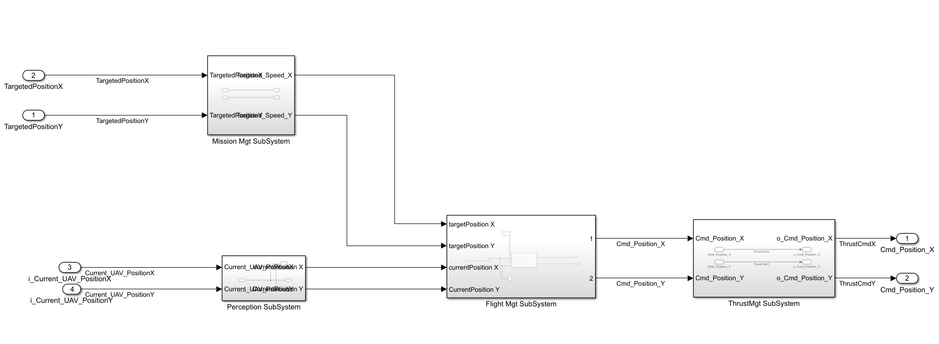
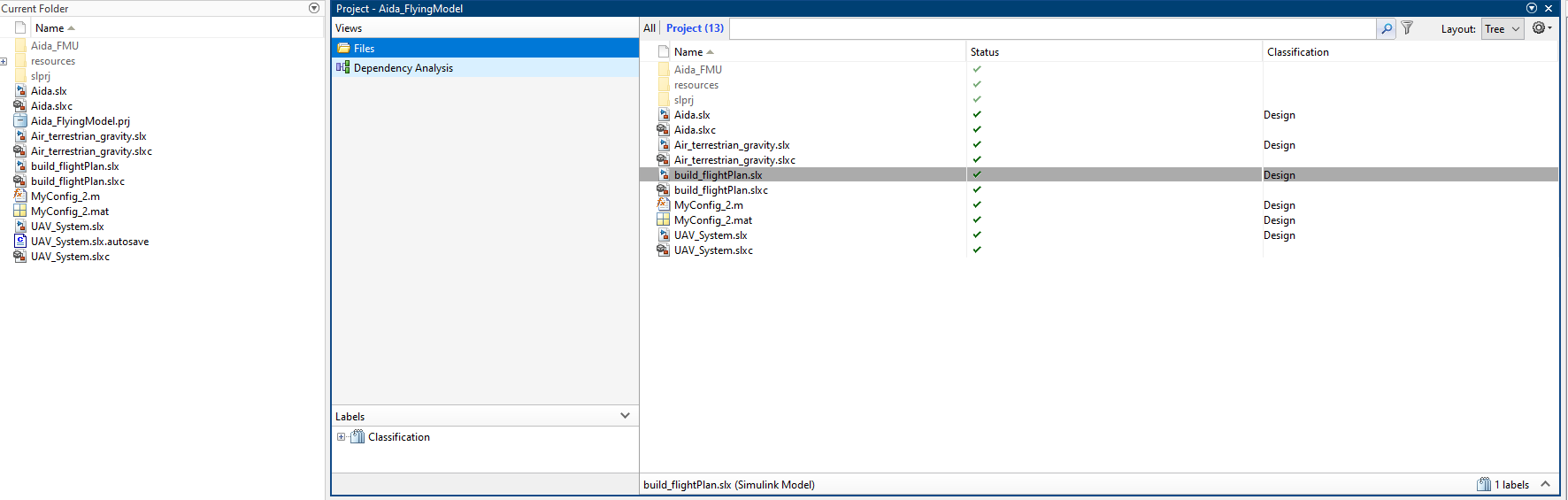
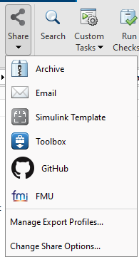
When a supplier has finalised the Simulink behavioural model and has tested it through simulation, it is then possible to create a MATLAB/Simulink project and share its contents as an FMU for Co-simulation:
Generation of Functional Mock-Up Unit from OpenModelica
When a behavioural model has been developed and simulated successfully on the supplier side, the Modelica model can be exported as an FMU:
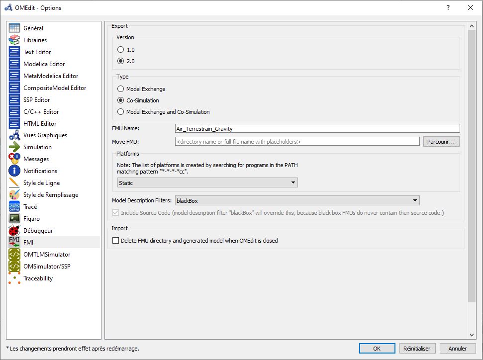
The supplier should configure the FMI options in the OMEdit configuration window:
Finally, the supplier can export Functional Mock-Up Unit for Co-Simulation.
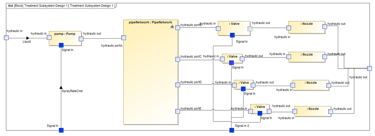
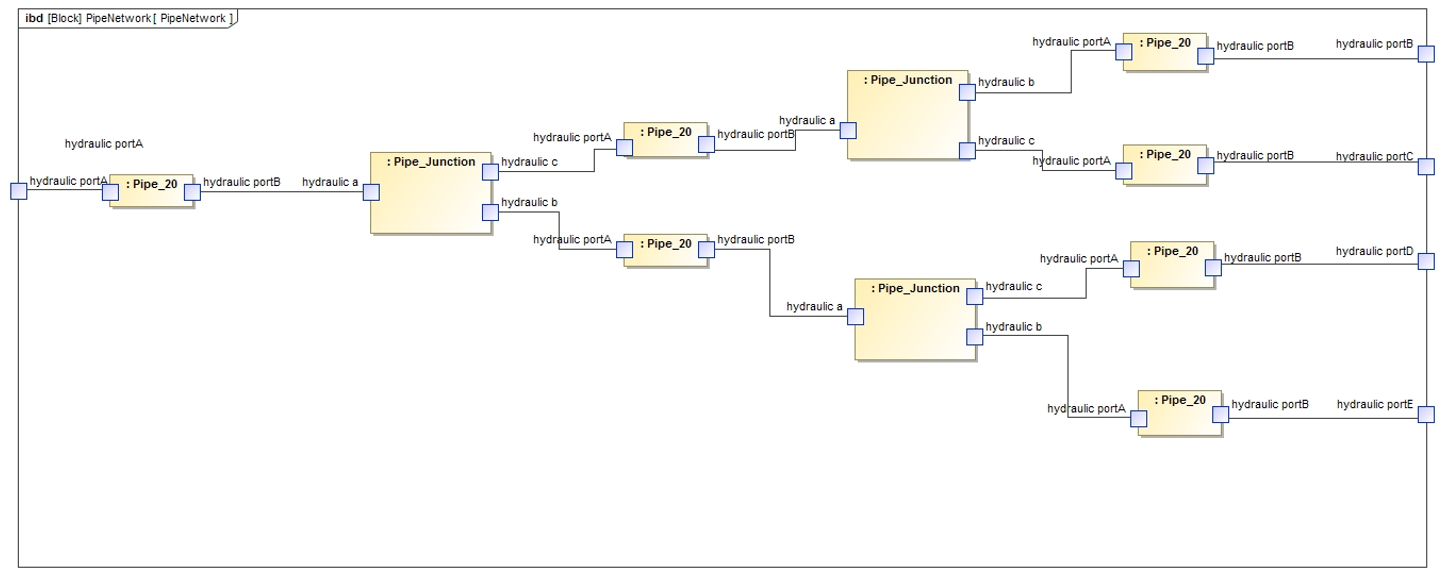
Assembly and execution of Functional Mock-Up Units in Cameo
When all the Functional Mock-Up Units have been received from suppliers as “black-box” executable models, the System Integrator can assemble these models. We can use the Cameo Systems Modeler tool and the Cameo Simulation Toolkit features to verify interface compatibility and the overall behaviour execution.
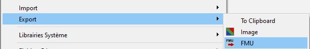
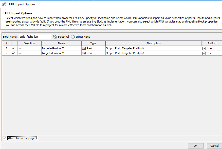
To perform this action, Cameo systems Modeler (CSM) offers a drag & drop feature of an FMU into a SysML IBD (Internal Block Diagram) and proposes the following import menu:
When all the FMUs have been imported into the Cameo Systems Modeler project, it is possible to assemble them together and check the consistency of the interfaces in regards to the established specification:
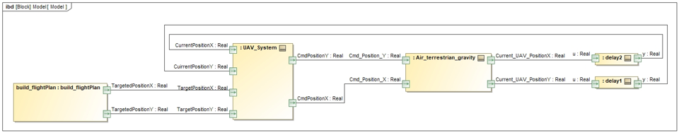
In order to simulate this model, it was necessary to “break” the feedback loop between Air Terrestrial Gravity and UAV System. This was done by inserting a “delay” component, which introduces a discrete delay (1/z) configured to 1 communication step size. This kind of annoying effect may appear depending on the tool used for FMU integration and on the underlying co-simulation master algorithm. We propose to address this topic in more detail in a future article.
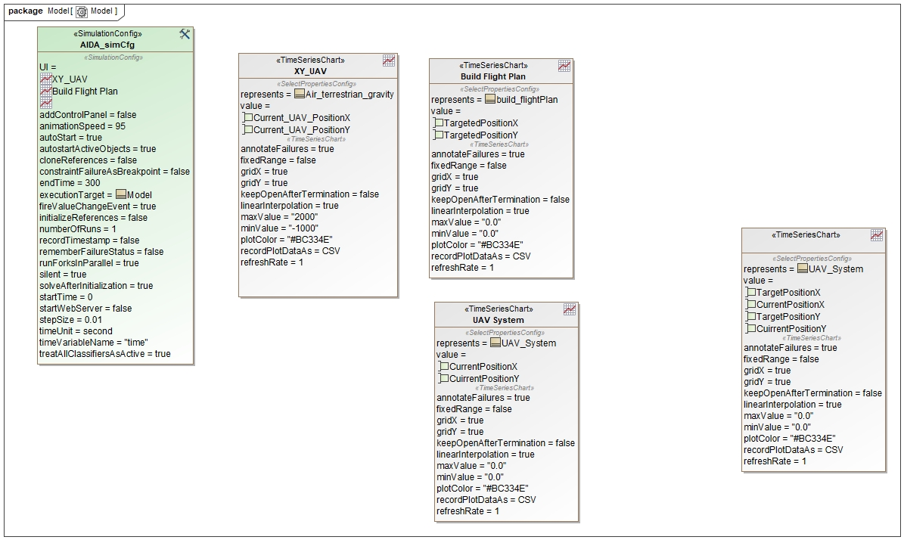
Next, the System Integrator is in charge of configuring the Simulation execution and especially the communication step size and the simulation duration. This configuration is done in the Simulation Configuration Diagram, as illustrated below:
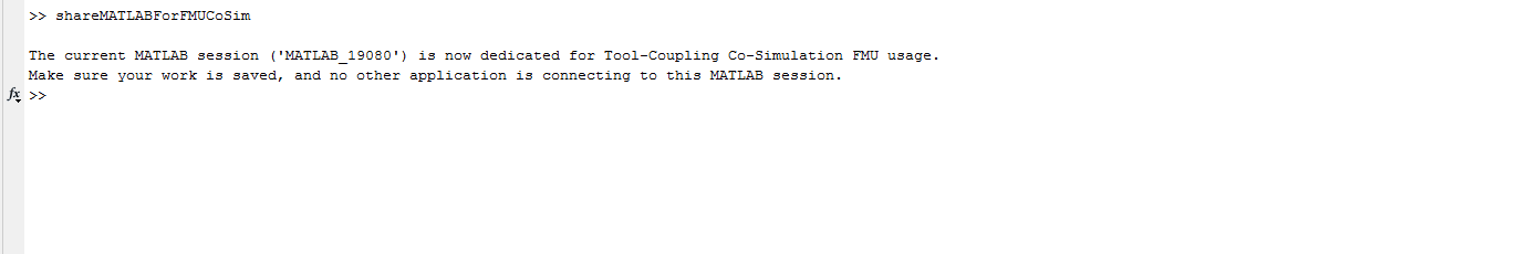
Now, before starting the simulation execution, it is necessary to launch the MATLAB Console for each MATLAB/Simulink FMU (at least for MATLAB/Simulink 2019b models) and execute the ShareMATLABforCosimFMU command (where communication between MATLAB FMU and MATLAB runtime is required).
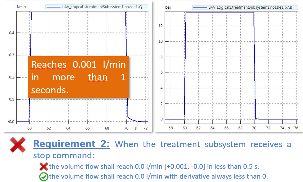
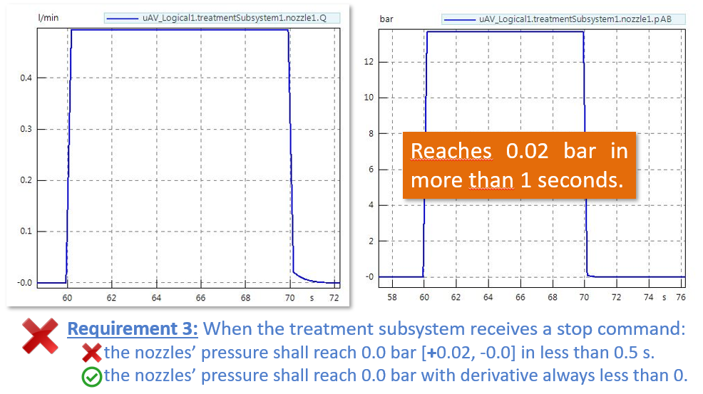
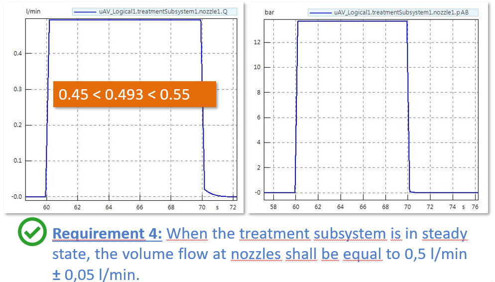
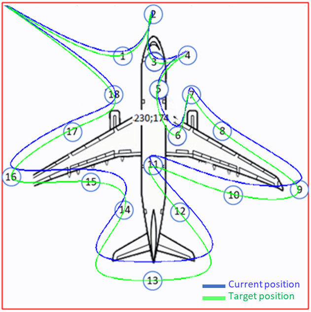
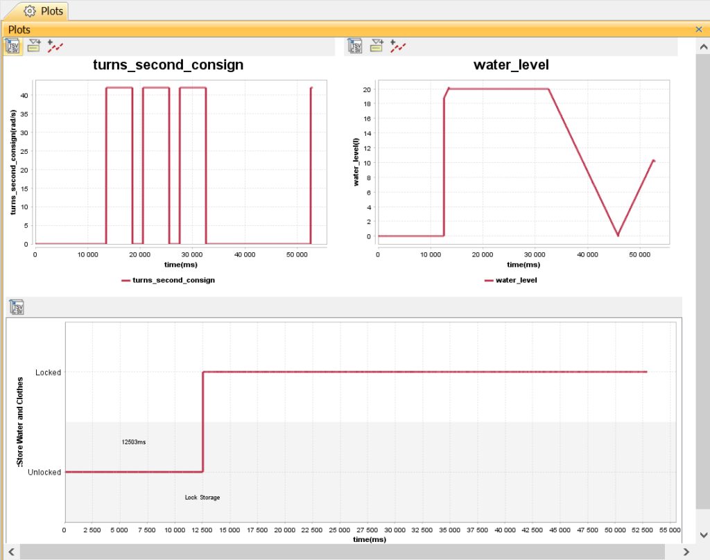
During simulation, the results can be observed from plots available in Cameo Systems Modeler, and it is possible to verify requirement compliance using co-simulation results inside Cameo:
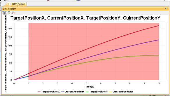
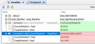
In the execution results, we can observe that the requirement (constraint) concerning the maximum error of 0.5 m between the target position and the real position is verified for the Y coordinate (constraint is respected, in green) but not for the X coordinate (constraint is violated, in red).
This approach makes it possible to detect requirement violations during co-simulation execution, which would have been very hard to detect without co-simulation, or that would have been detected later in the product verification, perhaps too late…
Synthesis
In this example, we have illustrated the capability to perform execution of heterogeneous FMUs (Modelica and MATLAB/Simulink) and co-simulate their execution within Cameo Systems Modeller. This capability allows for Systems Verification while collecting Systems artifacts behaviours from suppliers as Functional Mock-Up Units.
Then, the Systems Engineer can integrate these models in a co-simulation environment and define the appropriate communication time-step (hC) size for the FMUs communication. To define the appropriate time-step size, the Systems Engineer should consider the overall expected parameters, such as the overall simulation time, and signal and behaviour dynamics / periods.
Going further
In this article, the initial model was initiated manually from the SysML model. However, it would be possible to have a seamless code generation of Modelica partial models from the SysML models. Indeed, since partial models play the role of specification (interface contracts), it would be possible to adapt the approach to take into account the full process of configuration and change management.
Next, as Cameo Systems Modeler offers FMI co-simulation capabilities, it would be possible to generate and assemble FMUs from the Modelica models produced for some subsystems with FMUs generated from Simulink models (for the control subsystems). This would make it possible to characterize the co-simulation architecture from the logical architecture.
Then, it should be interesting to explore the usage of FMI standard companions such as System Structure & Parametrization (SSP) which supports standardization of co-simulation graph and configuration and Distributed Co-Simulation Protocol (DCP) which supports the standardization of communication protocols for co-simulation distributed on several execution nodes such as computers.
Finally, we plan to contribute to different initiatives (like the AFIS/NAFEMS working group) that aim at bridging the gap between system definition models developed by system architects with an MBSE approach, and detailed behavioural models sometimes called “simulation models” developed by domain specialists. The idea is to leverage the integration of those different models to address different purposes including feasibility, evaluation of performances, verification of system requirements and validation of expected behaviour.
Next articles about FMI/FMU
We consider the use of the FMI standard as a key practice to leverage the MBSE approach in extended enterprises. In future articles we plan to address the following complementary topics:
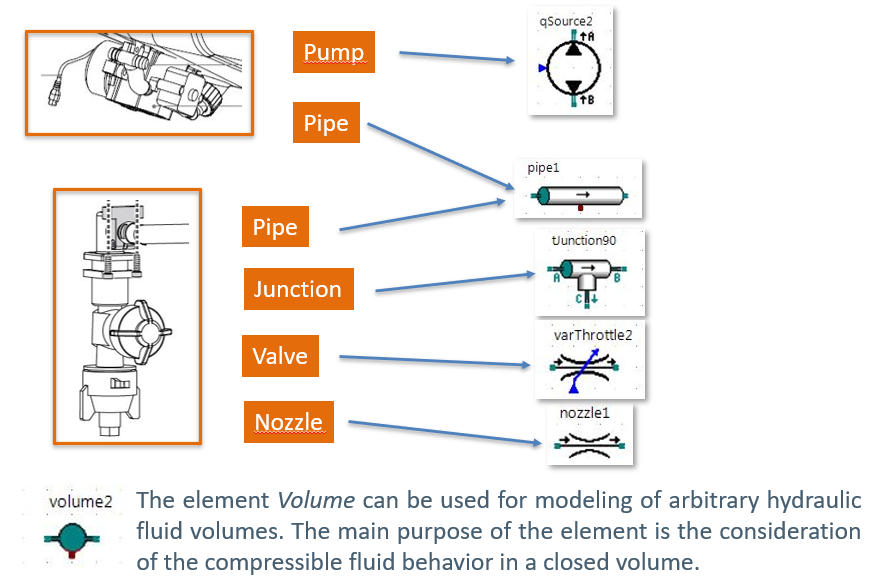
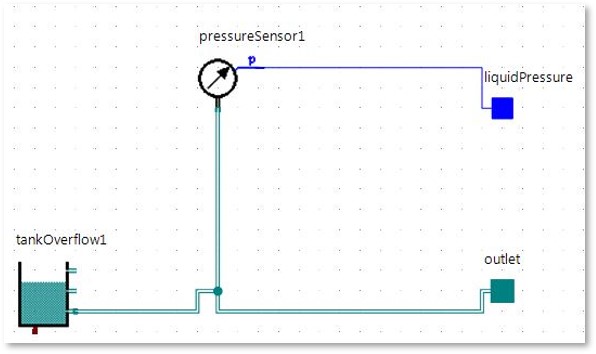
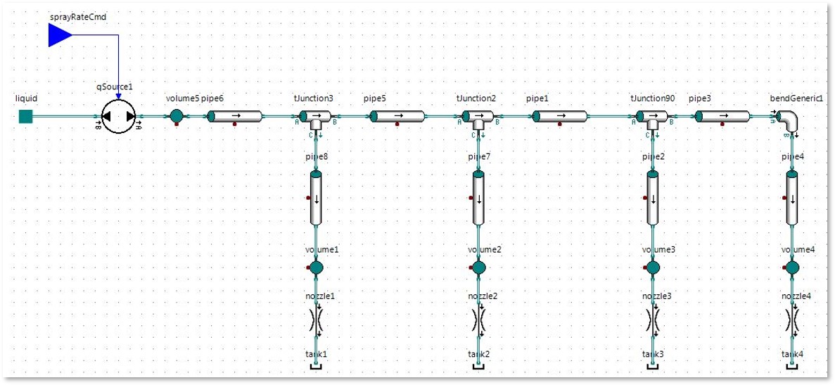
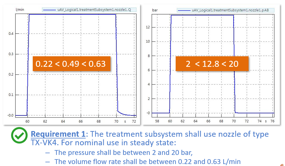
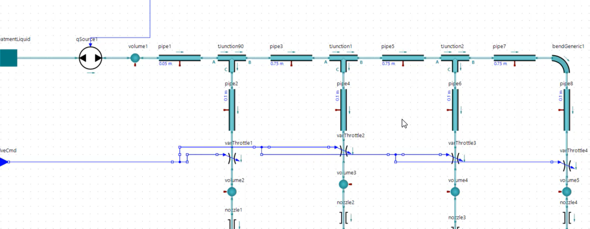
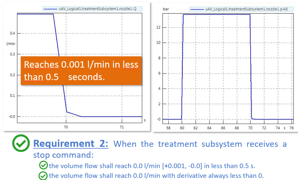
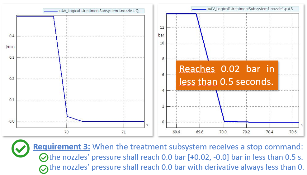
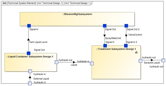
- Complex multi-physical model: in the current article, we addressed simplified Modelica and MATLAB/Simulink models for the Flight Control System. In a future article we plan to address a more complex multi-physical model which will combine discrete state machines behavioural models, control-command systems and physical acausal systems (pipes, fluids, mechanics, …).
- Mixing virtual and real systems: we plan to explore a progressive integration of real systems in combination with co-simulated systems to allow for an incremental Verification and Validation process.
- Connect operational scenarios with a simulated environment: we intend to detail the links between scenarios defined at the operational and functional architectural levels, scenarios used for Verification and Validation and to automate/link Simulation Environment and associated results.
- Provide feedback on the identification of the communication step size: Detail more complex models and give best practices to define the accurate value for the communication step size.
Enjoy MBSE !