Part 3 – Early validation of stakeholder needs through functional simulation
This article is part of a monthly series entitled “Advanced MBSE with SysML and other languages“.
In the first set of articles, this series explains how to use a modeling approach based on the SysML notation to progressively analyze, structure, refine and derive stakeholder needs and requirements into system architecture and lower-level requirements, down to configuration items containing software and hardware parts.
In the second set of articles, this series will focus on the links to other modeling languages used to detail the design and/or perform detailed analysis and simulations to evaluate, verify or validate the virtual representation of the system.
This third article puts a spotlight on a way to validate the stakeholder needs. We show how it is possible to use a modeling approach to structure and refine functional needs into a functional architecture. We also show that it is possible to simulate this functional architecture against operational scenarios expressed by the stakeholders. The simulation allows us to monitor some of the key system parameters and provides good support for validating stakeholder needs early in the development cycle.
Functional architecture is useful to support early validation of the system!
Sometimes we hear from some systems engineers that only the physical architecture is really useful to support validation. That is true if we target the end-product. At this stage, we need to get an architecture as close as possible with the reality (a characteristic sometimes called “fidelity”) to limit errors and wrong conclusions from the results of the simulation. But if we focus on the validation of functional requirements, it is not a good idea to wait too long before starting validation because we may be working with a wrong or incomplete capture of functional needs. And we can already do a lot to verify these needs early in the development cycle, even with a purely functional (virtual) representation of the end product.
In order to reach early validation, there are different activities to perform:
- The identification of the validation objectives
- The identification of the system functions and their functional interactions with system operational context
- The internal functional flows to support complete functional chains starting from operational scenarios.
Identification of the validation objectives
First, we need to identify what we want to validate. The most important thing to keep in mind is the rationale of why we developed our system of interest: the mission(s) to support! So let us focus on the mission(s) of our system of interest and check that our system is able to support the mission profile (set of phases and states) and its expected performance in the operational context. You may think that we need to know the complete physical architecture to measure this performance. Yes for the final detailed figures, but we can already approximate some elements and get a first rough idea without the full list of organs. We will see in the next paragraphs that we can add some behavior to the functions and then we can reach good support for the calculation of the system performance.
Identification of the system functions and their functional interactions with the operational context
This activity consists in mixing two approaches: the engineering knowledge of the solution coming from systems engineers experience on one hand, and the needs expressed by the different stakeholders on the other.
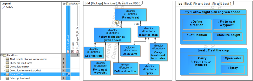
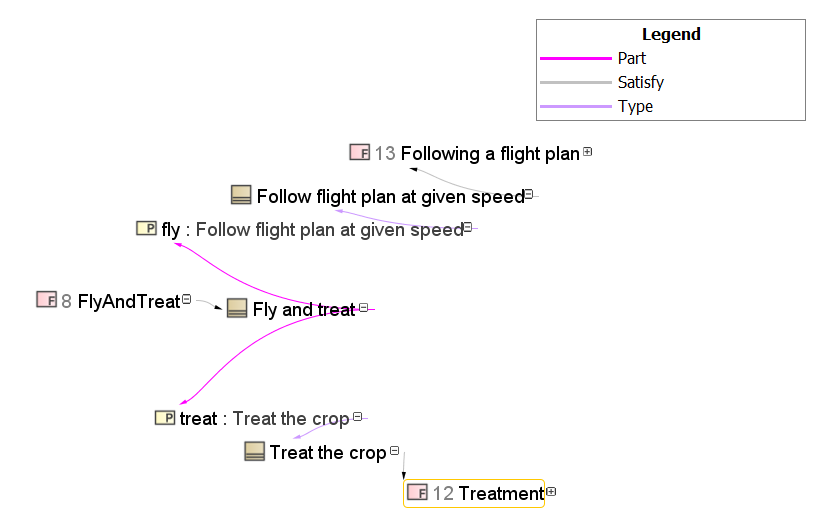
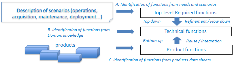
The systems engineers will through their experience provide a set of functions often called “technical functions” because they come from the knowledge of the technical solutions/products commonly used in a similar context. The expression of needs coming from the various stakeholders will lead to what we call “service functions” or “required functions”. These functions are generally identified through a set of scenarios that cover the different lifecycle concepts. The functional architecture will arrange the functions so that we can support top-level required functions with technical functions as illustrated below.
Now let us see in practice how we can use a model-based approach to support these activities.
At the French Chapter of INCOSE , called AFIS, in the MBSE technical committee, we have created a working group to discuss the use of functional model simulation as a means to reach early validation of the system functional requirements. We quickly discovered that it would be useful to compare our different approaches through a common sample case. And we have chosen a connected washing machine for this exercise. It is a system that everyone knows, at least as an end-user.
We use this sample case to illustrate the suggested approach.
A sample case to illustrate the use of a functional model simulation as a means for early validation…
Our sample case is a connected wasching machine. The “connected” part means that you can start and monitor the progress of the washing through your smartphone.
The description is available online here: https://www.samsung.com/fr/washing-machines/front-loading-ww90m645opw/

Concerning the functional behavior, we are not specialists and we have extracted knowledge from this web site (in french): https://www.spareka.fr/comment-reparer/electromenager/lave-linge/fonctionnement
Focus on the mission and identification of the operational scenarios
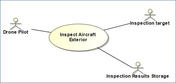
Let us start by looking at the missions / use cases for this system of interest. We want to be able to wash clothes, either directly or remotely (from our smartphone).
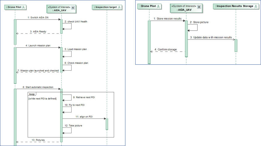
According to these use cases we have 2 main scenarios that describe the interactions between house habitants and the connected washing machine. We use “UC diagram” to represent the different system missions and we use “Sequence Diagrams” to represent the interactions, as illustrated below:
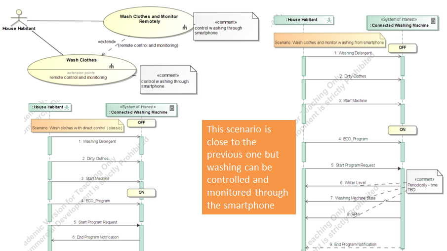
Note: these sequence diagrams are simple and this is on purpose. We do not introduce advanced logics like loop, parallel, or alternatives to keep the diagram very simple and easy to review by end-users and customers who are not necessarily familiar with the SysML notation.
From an operational scenario to a validation scenario…
The different operational scenarios defined previously (through Sequence Diagrams) can be reused as skeletons for the future validation of the system. You may ask: “What is the difference between an operational scenario and a validation scenario?” A validation scenario is more detailed than the operational scenario. It contains the same list of interactions but also some additional elements:
- Concrete values for the different stimuli sent to the system (from external systems or humans)
- Some delays between interactions in order to reflect human behavior (a human is not a robot that can immediately trigger the stimuli one after the other)
- Some observations about the system behavior during the mission
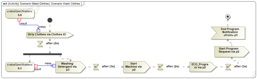
We can use an activity diagram to formalize a validation scenario. It can be translated from the operational scenario quite easily:
- Each input message is translated into a “send signal action” so that we can send a signal to the system
- Each output message coming back to the operator is translated into an “accept event action” that waits for the arrival of the signal.
Then let us see how we complete this scenario to allow some validation.
- The concrete values used as inputs for the stimuli are formalized with the “ValueSpecification” concept and are transmitted to the “send signal actions” through “object flow“. In the example shown below, we load 5 Kg of dirty clothes and 0,1 liter of detergent.
- The delays between the human interactions are formalized with the use of “AccceptTimeEvent” with a delay expressed in “relative” mode (after XX seconds).
- The observations are detailed in the next paragraph.
Identification of the functions
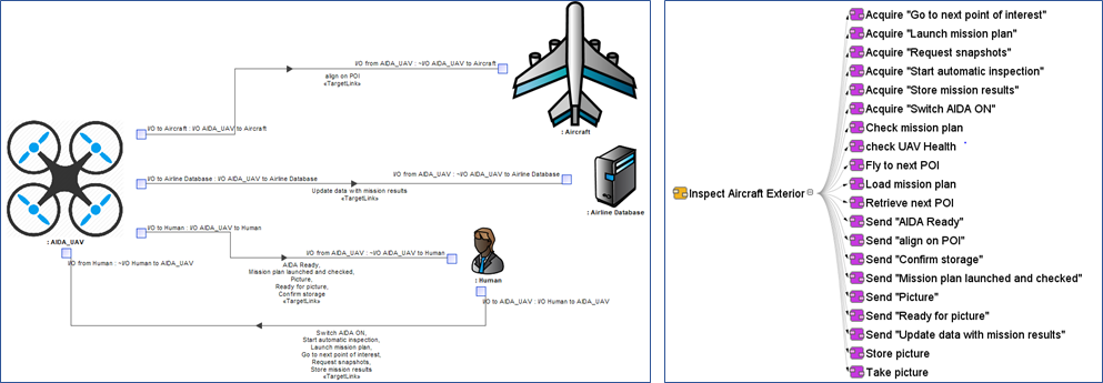
We start the identification of the functions by looking at the system operational context. It gives us the inputs and outputs of the system. We can use an Internal Block Diagram (IBD) to represent this context.
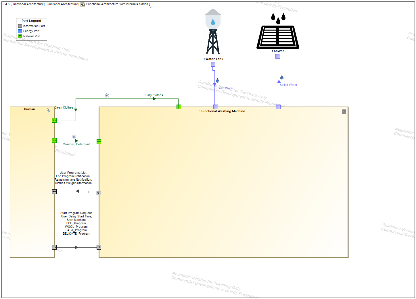
Note: we distinguish different types of flows: information, energy, and Matter. We use SysML stereotypes (additional semantics to SysML concepts) in order to manage those specialized flows and associated ports. We can associate a given color and a given icon for each stereotype, which makes the reading easier. A legend is available on the top left of the diagram.
Then the functions are identified by following some simple patterns:
- The interactions from our System with its context (physical environment, other connected systems, and human interactions) are encapsulated with interface functions that are in charge of managing those interactions.
- in our sample case, we find “Manage Human interaction” and “Manage Water“
- The mission progress is managed by a dedicated function. In our sample case, it is called “Manage Washing Program“
- Finally, we add all the functions required to manage human interactions and to support the mission
- In our case, we add “Store Water and Clothes” to ensure the human interaction concerning clothes
- We add “Provide Washing Movement” to clean the clothes.
We represent the usage of those functions as “part properties” inside our System Of Interest (SoI).
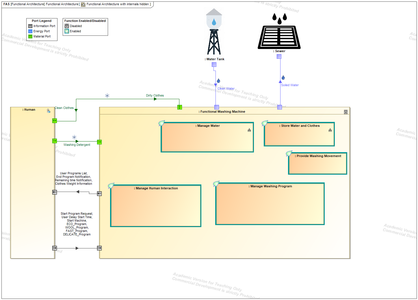
Note: the functions are all enabled by default in this diagram but some may be disabled by other functions in some conditions during system execution. The function adornment would then change with a new symbol as explained in the legend (top left of the diagram).
Support of service functions with technical functions
When we get a good idea of our service functions identified from operational scenarios and from the operational context, we get 2 options: either we are able to specify their behavior (to support functional simulation) or we consider that the function is too complex or has too many objectives and then we refine it with lower-level technical functions. In that case we use our engineering knowledge to identify those technical functions.
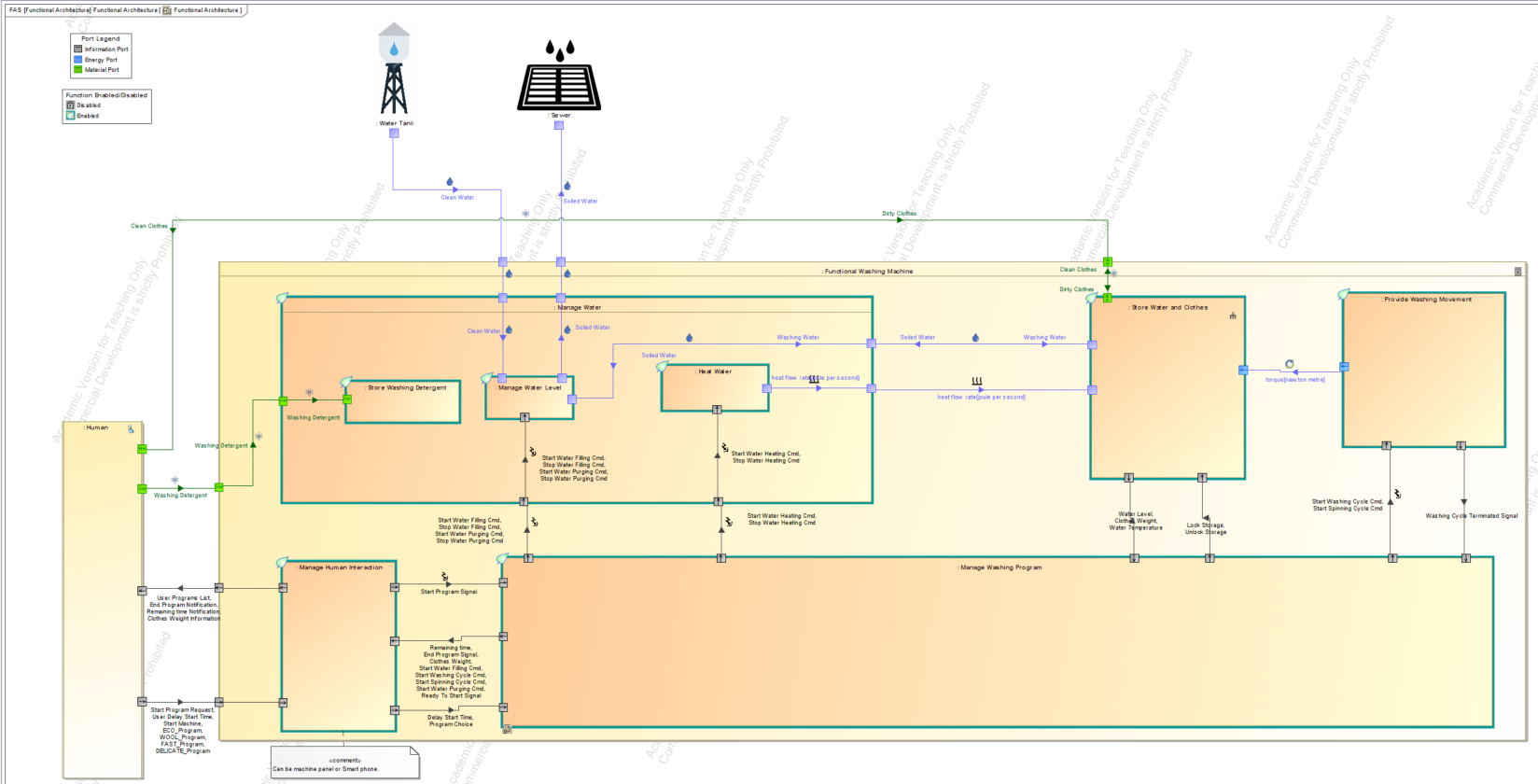
In our case, the “manage Water” function is still complex and needs to be refined into lower-level technical functions. From the website used to understand the washing machine behavior, we learn that we need several functions to manage the water. We need to manage the water level, to heat the water and to store the washing detergent. We connect these functions with the external environment (water supply and sewer, human interactions) . We use an IBD to show this refinement:

Observations of the SoI to reach validation objectives – support by function behavior
Now we want to ensure that we can observe our system in order to check that the system behaves as expected and supports the mission performance. Once we have identified all key parameters to monitor we will be able to define the functional behavior required to compute those key parameters and to carry them to the end-user.
What are the key elements we want to observe from our system of interest seen as a black box?
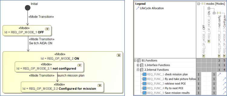
- First, we want to see the mission progress for which the system is being developed. In our sample case, we want to monitor the state of the program over time: is it filling the water? washing the clothes? purging the water? spinning the clothes?…
- We use a dedicated function to manage the mission states (as presented previously) and a state machine diagram to represent the different states and their transitions over time
- This state machine can be simulated using the Cameo Simulation Toolkit as illustrated below
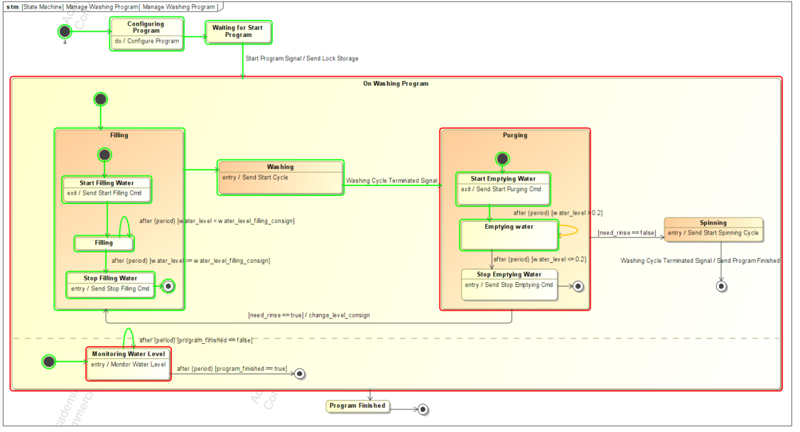
Note concerning the colors:
The “Red” color represents the current active state during the simulation session.
The “Green” color represents all the states that have been simulated since the beginning of the simulation session.
The “yellow” color represents the current transition being triggered (if any)
- Then we want to verify the Measures of Effectiveness (MoEs). These are the measures used to ensure that the mission is successful in its operational context. We want to be sure that the system will fulfill its mission with accurate performance. In order to do that, we need to monitor the key system parameters used to calculate the MoEs over time: water level, nb turns per minute, remaining time…
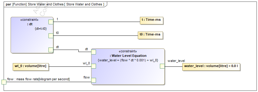
- We use equations and parametric diagrams to bind the system key parameters with the equation parameters when there are continuous flows (like the water flowing in and out).
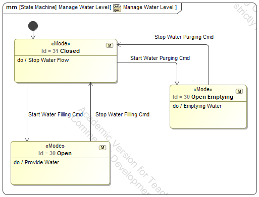
- Concerning the water level management, we just need to focus on the modes of the function. This can be done through the use of a state machine. Transitions are triggered on key events that come from the control of the washing program steps. And for each “state” we define a simple behaviour with a simple “Activity” element (using the “DoActivity” to reference those activities).
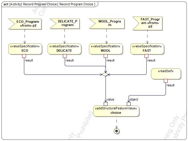
- Concerning the human interactions, we can use an activity diagram to represent the configuration of the program, as illustrated below:
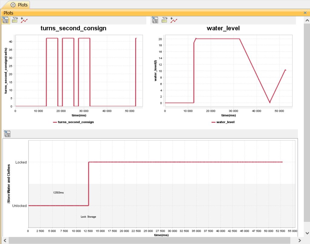
- Finally, we want to visualize the different MoEs in a synthetic way. We can use plots (provided by Cameo Simulation Toolkit) to show the different curves of the key parameters over time
Finalization of the functional architecture
The system functional architecture is finalized by connecting all the system functions with the SoI operational context and with each other using internal flows.
3 kinds of functional flows
Each functional flow can be of 3 different kinds: information, energy or material. By using different icons and colors to represent those different kinds, it gives the reader immediate feedback and makes the diagram easy to read. The reader can easily focus on one given kind.
We want the functional architecture to support simulation. It means that each function must have an associated behavior that can be executed (simulated). According to the function, we can use the different following behaviours:
- State machine (introduced previously to represent the states of the function “Manage Washing Program” over time)
- Parametric diagram (introduced previously to represent a differential equation with regards to water level over time)
- Activity diagram to complete a state machine diagram or to specify some constant values as illustrated previously for function “manage human interaction”
Note: we can also use an opaque behavior to represent an external behavior such a Matlab function or Modelica equation or a Functional Mockup Unit (see FMI standard for more information about that).
Driving the simulation with graphical support
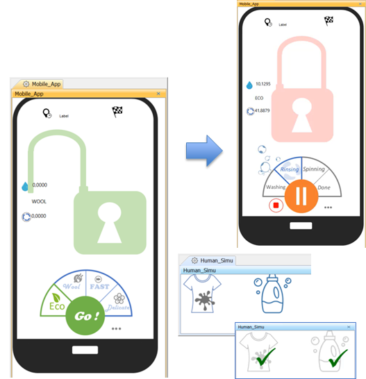
- Finally, we may also want to drive the simulation using a Human Machine Interface (HMI) mock-up that reflects the future operations performed by the end user. In our case, a person can use his/her smartphone to drive and monitor the progress of the washing.
- For this purpose we can use dedicated widgets provided by the Cameo Simulation Toolkit to represent the future HMI and bind some system states with panels or images as illustrated below:
Can we automate some of the steps presented above?
Yes.
We have created a plugin to automate the transformations between the operational scenarios and the validation scenarios. We still need to complete those validation scenarios but this is easy to do when the list of interactions has already been translated from the sequence diagrams.
We have also defined a dedicated functional architecture editor (called FAS for “Functional Architecture Synthesis”) that provides support for the choice of the different kinds of functional flows and that can create the function ports automatically when needed to ensure the encapsulation principle (all functional flows are passed through the ports of the parent function).
Simulation in practice (video)
Look at the video at the bottom to see 3 validation scenarios executed through model simulation.
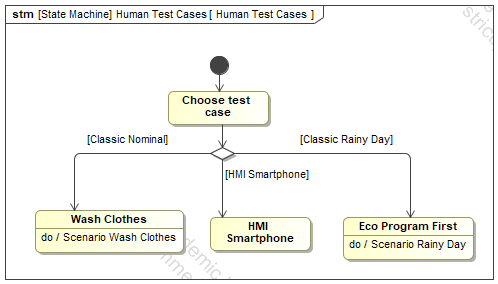
In the first scenario, we use the simulation console to monitor the key parameters’ values during the simulation in addition to the plots that show the progress over time.
In the second scenario, focus is put on the HMI used to drive the scenario (representing a smartphone). There is no use of the simulation console: both the control and the monitoring is done through this HMI.
The last scenario is a rainy day scenario. It shows that it is possible to describe dysfunctional scenarios and use them to see how the system behaves in abnormal conditions.
Enjoy MBSE!
Next articles to come…
- July 2020 -Consistency between functional and logical architectures
- August 2020 – Minimization of the coupling in the logical architecture
- September 2020 – Digital continuity between SysML and Simulink
- October 2020 – Digital continuity between SysML and AADL
- November 2020 – Digital continuity between SysML and Modelica
- December 2020 – Co-simulation of SysML and other models through FMI
Previous articles in the series
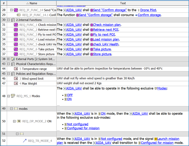
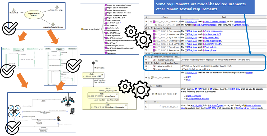
- April 2020 – Formalization of functional requirements
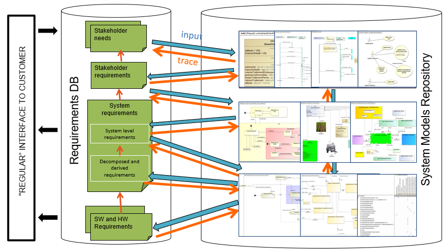
- May 2020 – Derivation of requirements from models: From DOORS to SysML to DOORS again